





TRUSTED BY THE SMARTEST TEAMS IN THE WORLD FOR CERTIFIED CANDIDATES
SPOTO Blogs
Useful learning materials to become certified IT personnel
-
- 341
- SPOTO
- 2026-07-31 15:30
-
- 406
- SPOTO
- 2026-07-31 15:16
-
- 326
- SPOTO
- 2026-07-31 14:45
-

- 711
- SPOTO 2
- 2026-07-31 10:38
-
- 305
- SPOTO
- 2026-07-30 14:20
-
- 254
- SPOTO
- 2026-07-30 14:06
-
- 310
- SPOTO
- 2026-07-30 14:02
-
- 317
- SPOTO
- 2026-07-30 11:08
-
- 648
- SPOTO 2
- 2026-07-14 10:18

TRUSTED BY THE SMARTEST TEAMS IN THE WORLD FOR CERTIFIED CANDIDATES
SPOTO Blogs
Useful learning materials to become certified IT personnel
-
- 341
- SPOTO
- 2026-07-31 15:30
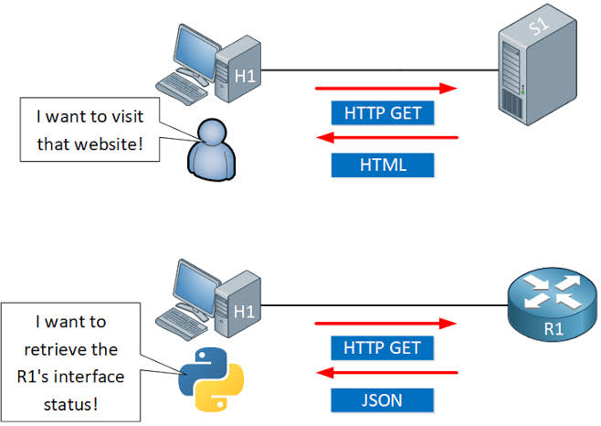
Table of ContentsUnderstanding Cisco REST API Architecture and Automation BasicsCisco REST API vs RESTCONF vs NETCONF: Choosing the Right ProtocolCisco REST API Authentication and Request TemplatesFixing Common Cisco REST API Errors: 401s, Token Expiration, and Timeouts Manually logging into dozens (or thousands) of Cisco devices to push configuration changes doesn't scale — and it's exactly the problem Cisco's REST APIs were built to solve. By exposing device and controller functionality over standard HTTP methods, Cisco REST APIs let engineers automate provisioning, monitoring, and troubleshooting through code instead of CLI sessions. This guide covers how the architecture works, how it stacks up against NETCONF and RESTCONF, hands you working Python and Postman templates, and shows how to resolve the authentication errors that trip up almost everyone the first time they call the API. Understanding Cisco REST API Architecture and Automation Basics Cisco REST APIs follow the same architectural pattern used across the broader software industry: resources (devices, interfaces, policies, sites) are represented as objects, and standard HTTP methods — GET, POST, PUT, DELETE — are used to read or modify them. Most Cisco automation platforms, including DNA Center, Meraki, and ACI, expose their functionality this way rather than requiring engineers to script raw CLI commands. Here's how the architecture fits together in practice: A controller or device exposes an API endpoint. Rather than automating individual routers and switches one by one, most modern Cisco automation happens against a central controller (like Catalyst Center, formerly DNA Center) that manages many devices underneath it. Requests are authenticated before any data is exchanged. Cisco platforms typically use token-based authentication — you authenticate once, receive a session token, and attach that token to subsequent requests instead of resending credentials every time. Data is exchanged as JSON. Both the request bodies (when creating or updating resources) and the response payloads (when reading data) use JSON, which is easy to parse and generate from almost any scripting language. Responses use standard HTTP status codes. A 200 means success, a 401 means an authentication problem, a 404 means the resource doesn't exist, and so on — this predictability is what makes REST APIs so much easier to script against than screen-scraping CLI output. Automation scripts or orchestration tools call the API in place of manual configuration. Common use cases include bulk device onboarding, automated compliance checks, dynamic VLAN provisioning, and pulling real-time telemetry into monitoring dashboards. This model works well for controller-driven, JSON-based automation — but it isn't the only protocol Cisco supports for network management. Understanding where REST fits relative to NETCONF and RESTCONF will help you pick the right tool for your environment. Cisco REST API vs RESTCONF vs NETCONF: Choosing the Right Protocol Cisco devices and controllers support several management protocols, and the differences between them affect how well they fit your automation strategy. Feature Cisco REST API (Platform-specific) RESTCONF NETCONF Data format JSON JSON or XML XML Data modeling standard Vendor/platform-defined YANG-based YANG-based Transport HTTPS HTTPS SSH (typically port 830) Best suited for Controllers (DNA/Catalyst Center, Meraki, ACI) Direct device configuration with structured models Direct device configuration with structured models and transactional changes Configuration validation Platform-dependent Strong, via YANG models Strong, via YANG models Transactional commits (candidate config, rollback) Rarely supported Limited Fully supported Learning curve Low to moderate Moderate (requires YANG familiarity) Higher (requires YANG familiarity and NETCONF operations) In practice, most enterprises end up using more than one of these depending on the layer they're automating. Cisco's platform-specific REST APIs (on DNA Center, Meraki, or ACI) are usually the fastest way to automate at the controller/orchestration level, since they're purpose-built around each platform's own resources. RESTCONF and NETCONF, by contrast, shine when you need standardized, YANG-modeled configuration directly on individual devices — NETCONF in particular is preferred when transactional safety (validate-then-commit, automatic rollback) matters more than ease of use. If your automation strategy centers on a Cisco controller, the platform's own REST API is usually the right starting point — and the templates below will get you making calls quickly. Cisco REST API Authentication and Request Templates Below are ready-to-use templates for authenticating and making calls to Cisco DNA Center / Catalyst Center-style REST APIs. Adjust the base URL and credentials for your platform. python # --- Python: Authenticate and retrieve a token --- import requests from requests.auth import HTTPBasicAuth BASE_URL = "https://[controller-ip]" USERNAME = "[username]" PASSWORD = "[password]" auth_response = requests.post( f"{BASE_URL}/dna/system/api/v1/auth/token", auth=HTTPBasicAuth(USERNAME, PASSWORD), verify=False # Set to True with a valid cert in production ) token = auth_response.json()["Token"] # --- Python: Use the token to call an API endpoint --- headers = { "X-Auth-Token": token, "Content-Type": "application/json" } devices = requests.get( f"{BASE_URL}/dna/intent/api/v1/network-device", headers=headers, verify=False ) print(devices.json()) # --- Postman: Authentication request --- Method: POST URL: https://[controller-ip]/dna/system/api/v1/auth/token Authorization: Basic Auth (username / password) # --- Postman: Authenticated GET request --- Method: GET URL: https://[controller-ip]/dna/intent/api/v1/network-device Headers: X-Auth-Token: {{token}} Content-Type: application/json # --- cURL equivalent --- curl -k -X POST "https://[controller-ip]/dna/system/api/v1/auth/token" \ -u [username]:[password] curl -k -X GET "https://[controller-ip]/dna/intent/api/v1/network-device" \ -H "X-Auth-Token: [token]" These templates cover the core authenticate-then-call pattern used across most Cisco REST APIs. The most common place automation breaks, though, isn't the request logic itself — it's authentication and token handling once scripts run unattended. Fixing Common Cisco REST API Errors: 401s, Token Expiration, and Timeouts Authentication-related failures are by far the most frequent issue engineers run into when automating against Cisco REST APIs. Work through these steps when a script that used to work suddenly starts failing. Confirm the token hasn't expired. Most Cisco controller tokens are short-lived (often around an hour). If a long-running script or scheduled job suddenly starts returning 401 Unauthorized, the token has likely expired mid-run — build in logic to re-authenticate and refresh the token before it lapses, rather than authenticating once at the start of a long process. Check that the token is being sent in the correct header. A surprisingly common cause of persistent 401 errors is simply sending the token in the wrong header name or format — double-check the platform's documentation for the exact header expected (e.g., X-Auth-Token versus an Authorization: Bearer header, which varies by Cisco platform). Verify the account has the right role and permissions. A valid token can still produce 401 or 403 errors if the authenticated user lacks permission for that specific API endpoint — check the user's role assignment on the controller. Resolve SSL certificate validation failures. If requests fail with certificate errors rather than clean HTTP status codes, it's usually because the controller is using a self-signed certificate. For production scripts, install the proper certificate chain rather than permanently disabling verification, which should only be used temporarily in lab environments. Diagnose connection timeouts separately from authentication errors. A timeout with no HTTP response at all usually points to a network reachability issue, a firewall blocking the API port, or the controller being overloaded — check basic connectivity to the controller's management interface before assuming it's an API-level problem. Add retry logic with backoff for transient failures. Controllers under heavy load may intermittently reject valid requests; a short retry with exponential backoff resolves most of these without masking genuine, persistent errors. Working through token validity, header formatting, permissions, and connectivity in that order resolves the overwhelming majority of Cisco REST API errors without needing to dig through controller logs. -
- 406
- SPOTO
- 2026-07-31 15:16
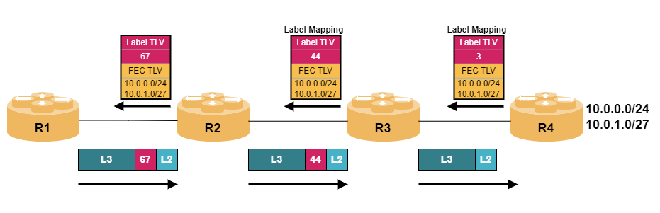
Table of ContentsTroubleshooting an LDP Neighbor Down: The Systematic WorkflowTargeted LDP vs. Link-Local LDP: Key Structural DifferencesTransport Address Mismatches and TCP Port 646 FailuresLDP Neighbor Troubleshooting Command Cheat Sheet: Cisco and Juniper An LDP neighbor showing "down" is one of those MPLS problems that can stem from several completely different layers — IGP reachability, a UDP discovery mismatch, a blocked TCP session, or a targeted-versus-link-local configuration mismatch. Because the symptom looks identical regardless of cause, working through the right layers in the right order is what separates a five-minute fix from an hour of guessing. This guide walks through a systematic troubleshooting workflow, compares the two LDP discovery mechanisms, digs into the transport-layer issues that trip people up most, and closes with a full verification command reference across Cisco and Juniper. Troubleshooting an LDP Neighbor Down: The Systematic Workflow LDP session establishment happens in two distinct phases — UDP-based discovery, then a TCP-based session — and knowing which phase is failing narrows the cause dramatically. Confirm IGP reachability between the two routers first. LDP relies entirely on the underlying IGP (OSPF, IS-IS, etc.) for reachability to the neighbor's transport address — if the IGP itself doesn't have a route to that address, LDP has no chance of establishing a session regardless of anything else being correctly configured. router# show ip route <neighbor-transport-address> Check whether LDP discovery (Hello) is happening at all. LDP Hello packets are sent via UDP to port 646, either as link-local multicast (for directly connected neighbors) or as targeted unicast (for non-directly-connected neighbors) — confirm Hellos are being seen before assuming the problem is deeper in the TCP session. router# show mpls ldp discovery Check the current LDP neighbor/session state. This tells you not just whether the session is up or down, but often the specific reason, if the platform surfaces one. router# show mpls ldp neighbor Determine whether the failure is at discovery (UDP) or session (TCP) stage. If discovery shows the neighbor but the session never establishes, the problem is almost certainly TCP port 646 connectivity or a transport address mismatch — covered in depth in the next section. If discovery itself shows nothing, the problem is more likely IGP reachability, interface-level LDP enablement, or a mismatched Hello interval/hold time. Confirm LDP is actually enabled on the correct interface. A surprisingly common cause of "no discovery at all" is simply forgetting to enable LDP on the interface facing the neighbor, especially after an interface was reconfigured or replaced. router# show mpls interfaces Check for a label distribution protocol mismatch. Confirm both routers are actually running LDP (rather than one running the legacy Tag Distribution Protocol, or a mismatched RSVP-TE-only configuration) — an obvious check, but one worth confirming explicitly rather than assuming. router# show mpls ldp parameters Check for MTU-related session instability. Similar to other control-plane protocols, an MTU mismatch across the link can cause LDP sessions to flap rather than simply fail to establish — if the session comes up briefly and drops repeatedly rather than never forming at all, suspect this before deeper configuration issues. router# show interfaces <interface> | include MTU Re-verify after each change, one variable at a time. As with most control-plane troubleshooting, changing multiple things simultaneously makes it much harder to know what actually fixed the problem — confirm neighbor state after each individual adjustment. router# show mpls ldp neighbor detail This layered approach — IGP reachability, then discovery, then session establishment — mirrors how LDP itself builds a relationship, which is exactly why working through it in this order consistently narrows down the cause fastest. Targeted LDP vs. Link-Local LDP: Key Structural Differences Not every LDP neighbor relationship is discovered the same way, and knowing which type you're dealing with changes what you should check first. Criteria Link-Local (Basic) LDP Targeted LDP Discovery mechanism UDP multicast Hello sent directly on a shared link UDP unicast Hello sent to a specific, often non-directly-connected, address Typical use case Directly connected MPLS-enabled links between adjacent routers Non-directly-connected neighbors, such as across a Layer 2 access network, for pseudowire/VPLS setups, or session backup/redundancy scenarios Configuration requirement Usually automatic once LDP is enabled on the interface Requires explicit configuration specifying the target neighbor's address Dependency on IGP Relies on IGP only for the transport address resolution used during TCP session setup, not for Hello delivery itself (which is link-local) Relies fully on IGP reachability for both Hello delivery (since it's unicast, routed) and transport address resolution Common failure mode Interface-level misconfiguration (LDP not enabled), or a directly connected Layer 1/2 issue Missing or incorrect target address configuration, or a routing path failure between the two non-adjacent routers Diagnostic starting point Confirm LDP is enabled on the correct interface first Confirm the targeted neighbor statement is present and the address is reachable via the IGP first Common Cisco config command mpls ip on the interface mpls ldp neighbor <address> targeted The practical distinction that matters most for troubleshooting: a link-local LDP failure is almost always a Layer 1/2 or interface-configuration problem local to that link, while a targeted LDP failure is almost always a routing (IGP) or explicit-configuration problem — start your investigation in the layer that matches which type of session you're actually dealing with. Transport Address Mismatches and TCP Port 646 Failures When LDP discovery succeeds but the session never actually establishes, the problem has moved from the UDP discovery phase into the TCP session phase — and this is where transport address and connectivity issues live. Understand what the LDP transport address actually is. After discovery, LDP routers use a specific IP address — typically a loopback interface by default — to establish the actual TCP session on port 646. This transport address is advertised within the Hello packet itself. Recognize the classic transport address mismatch scenario. If one router's advertised transport address isn't reachable from the other router (for example, its loopback isn't being advertised into the IGP, or is filtered), discovery can succeed via a directly connected interface while the TCP session fails, since the session attempt targets an address that can't actually be reached. Verify the transport address being advertised. router# show mpls ldp discovery detail Confirm the advertised transport address is reachable via the IGP. This is the single most common root cause of "discovery works, session doesn't" — check specifically for the transport address, not just the interface's directly connected address. router# show ip route <advertised-transport-address> Check for an access list or firewall blocking TCP port 646. Unlike the UDP Hello packets, the LDP session itself is TCP-based, so a stateful firewall or ACL that permits UDP 646 but blocks TCP 646 (or vice versa) will produce exactly this "discovery succeeds, session fails" pattern. router# show access-lists router# show ip access-lists interface <interface> Confirm the TCP session state directly if available on your platform. Some platforms expose LDP's underlying TCP connection state directly, which can confirm whether the router is even attempting the TCP handshake. router# show tcp brief | include 646 Fix a transport address mismatch by aligning IGP advertisement. If the issue is that a loopback used as the transport address isn't in the IGP, the fix is typically to ensure that loopback is included in the IGP's network statements or redistribution, or to explicitly configure LDP to use a different, already-reachable interface as its transport address. router(config)# mpls ldp router-id <interface> force Fix a blocking ACL by explicitly permitting TCP port 646 between the two routers. Make sure any ACL applied to the relevant interface allows both the UDP discovery traffic and the TCP session traffic — a common mistake is fixing one and forgetting the other. router(config)# ip access-list extended LDP-PERMIT router(config-ext-nacl)# permit tcp host <router-a-ip> host <router-b-ip> eq 646 router(config-ext-nacl)# permit udp host <router-a-ip> host <router-b-ip> eq 646 Re-verify the full session state after resolving transport or ACL issues. Confirm the session moves from a discovery-only state to a fully established neighbor relationship, not just that traffic is no longer being blocked. router# show mpls ldp neighbor detail Once the transport address is confirmed reachable via the IGP and any ACLs or firewalls explicitly permit both UDP and TCP traffic on port 646, LDP sessions that were stuck at the discovery stage almost always complete and move to established state without further intervention. LDP Neighbor Troubleshooting Command Cheat Sheet: Cisco and Juniper For quick reference during troubleshooting, here's a consolidated command set covering discovery, session state, transport address, and platform-specific syntax across both major vendors. # --- Cisco IOS/IOS-XE: Discovery and neighbor state --- router# show mpls ldp discovery # Hello-based discovery status router# show mpls ldp discovery detail # Includes advertised transport address router# show mpls ldp neighbor # Current neighbor/session state router# show mpls ldp neighbor detail # Full session detail including timers # --- Cisco IOS/IOS-XE: Interface and parameters --- router# show mpls interfaces # Confirm LDP enabled per interface router# show mpls ldp parameters # Global LDP configuration/session parameters router(config-if)# mpls ip # Enable LDP on an interface (link-local) router(config)# mpls ldp neighbor <address> targeted # Configure targeted LDP session router(config)# mpls ldp router-id <interface> force # Set explicit transport/router ID # --- Cisco IOS/IOS-XE: Transport and connectivity checks --- router# show ip route <transport-address> # Confirm IGP reachability router# show access-lists # Check for blocking ACLs router# show tcp brief | include 646 # Check TCP session state directly # --- Juniper Junos: Discovery and neighbor state --- > show ldp neighbor # Current neighbor/discovery state > show ldp session # TCP session state and detail > show ldp session detail # Full session parameters > show ldp interface # Confirm LDP enabled per interface > show ldp database # Label bindings learned # --- Juniper Junos: Configuration --- # set protocols ldp interface <interface-name> # Enable LDP on an interface # set protocols ldp session <neighbor-address> # Configure targeted session # set protocols mpls interface <interface-name> # Enable MPLS on an interface # --- Cross-platform packet capture (last resort) --- router# debug mpls ldp transport events # Cisco: TCP transport events router# debug mpls ldp messages # Cisco: Hello/session message exchange Keep the "discovery detail" and transport-address reachability checks near the top of your workflow — in both Cisco and Juniper environments, that combination diagnoses the large majority of LDP neighbor-down cases faster than reaching for debug output. -
- 326
- SPOTO
- 2026-07-31 14:45
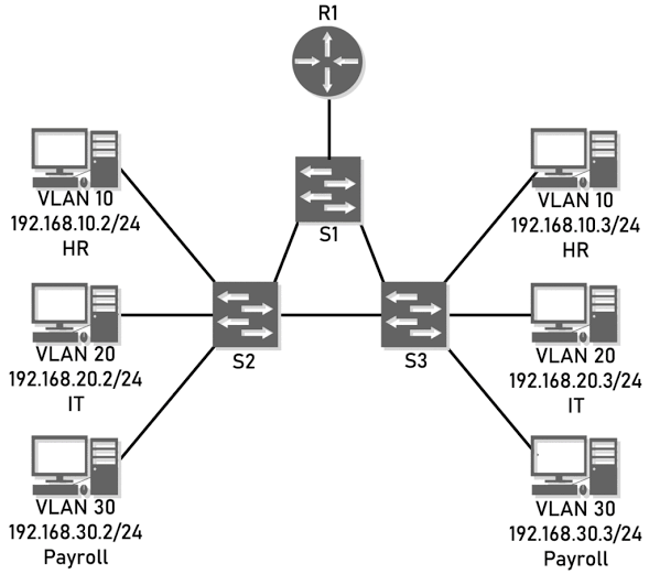
Table of ContentsAdvanced VLAN Configuration Scenarios for the CCIE LabPrivate VLANs vs. QinQ: Choosing the Right Isolation MechanismTroubleshooting VLAN Trunking, Native VLAN Mismatches, and VTPv3 Sync FailuresCCIE Lab VLAN Practice Workbook: Topology and Configuration TemplatesBringing It All Together Basic VLAN configuration barely scratches the surface of what the CCIE Enterprise Infrastructure lab actually expects. At this level, you need fluency with extended-range VLANs under VTP version 3, Private VLANs for sub-segmenting a broadcast domain, 802.1Q tunneling (QinQ) for carrying customer VLANs across a provider infrastructure, and the diagnostic instincts to fix trunking and VTP failures fast, under time pressure. This guide covers all four, building from advanced configuration scenarios through to a practice-ready command workbook. Advanced VLAN Configuration Scenarios for the CCIE Lab Beyond standard VLAN creation, the lab expects fluency with several advanced mechanisms working together. Here's how to approach each one. Master extended-range VLANs under the version that actually matters for the lab. Extended-range VLANs (1006–4094) require VTP transparent mode under VTP v1/v2, since those versions can't propagate or store them in the VLAN database. If the topology specifies VTP v3, extended VLANs are supported in server mode as well — know which version you're working with before troubleshooting a VLAN that "won't stick." switch(config)# vtp version 3 switch(config)# vtp mode server switch(config)# vlan 2000 switch(config-vlan)# name EXTENDED_LAB_VLAN Configure Private VLANs for sub-segmentation within a single broadcast domain. A private VLAN scenario typically asks you to isolate hosts sharing the same subnet without giving them full Layer 2 visibility of each other — start by defining the primary VLAN and its secondary (isolated or community) VLANs, then associate them. switch(config)# vlan 100 switch(config-vlan)# private-vlan primary switch(config)# vlan 101 switch(config-vlan)# private-vlan isolated switch(config)# vlan 100 switch(config-vlan)# private-vlan association 101 Assign host and promiscuous ports correctly. Private VLAN scenarios almost always test whether you understand which port type goes where — host ports connect end devices to the isolated/community VLAN, while the promiscuous port (typically facing a router or firewall) can communicate with every secondary VLAN under the primary. switch(config)# interface gigabitEthernet 1/0/10 switch(config-if)# switchport mode private-vlan host switch(config-if)# switchport private-vlan host-association 100 101 switch(config)# interface gigabitEthernet 1/0/1 switch(config-if)# switchport mode private-vlan promiscuous switch(config-if)# switchport private-vlan mapping 100 101 Configure 802.1Q tunneling (QinQ) for provider-style VLAN transparency. QinQ scenarios simulate a service-provider edge, where an entire customer's tagged VLAN traffic needs to cross the provider network inside a single outer (provider) VLAN tag, without the provider switches needing awareness of the customer's internal VLAN structure. switch(config)# vlan 300 switch(config-vlan)# name PROVIDER_TUNNEL switch(config)# interface gigabitEthernet 1/0/20 switch(config-if)# switchport access vlan 300 switch(config-if)# switchport mode dot1q-tunnel switch(config-if)# l2protocol-tunnel cdp Enable the global QinQ ethertype if the lab topology requires 802.1ad compliance. Some scenarios specifically test whether you know to change the tunneling ethertype from Cisco's default to the 802.1ad standard value, since interoperability with non-Cisco gear depends on it. switch(config)# vlan dot1q tag native switch(config)# ethertype 88a8 Verify every layer before moving to the next configuration task. In a timed lab environment, confirming each piece works immediately — rather than building the whole topology and testing at the end — saves far more time than it costs. switch# show vlan private-vlan type switch# show interfaces gigabitEthernet 1/0/20 switchport switch# show vtp status With PVLANs and QinQ both available as isolation tools, the natural next question in a lab scenario is which one actually fits the requirement being tested — and that's a distinction worth having memorized cold. Private VLANs vs. QinQ: Choosing the Right Isolation Mechanism Both technologies restrict Layer 2 visibility between devices, but they solve different problems and get tested differently in the lab. Criteria Private VLANs (PVLAN) 802.1Q Tunneling (QinQ) Primary purpose Isolate hosts within the same subnet/broadcast domain from each other Transparently carry a customer's multiple VLAN tags across a provider network inside one outer VLAN Scope of isolation Within a single VLAN (via primary/secondary VLAN pairs) Between the customer's VLAN structure and the provider's — customer VLANs stay invisible to the provider core Typical lab trigger phrase "Hosts must not communicate with each other but must reach the gateway" "Customer VLANs must traverse the provider network without provider switches learning about them" Port roles involved Host ports (isolated/community) and a promiscuous port Access ports in dot1q-tunnel mode facing the customer edge VLAN tag behavior Single VLAN tag; isolation enforced by port type, not by additional tagging Double-tagging — customer's original 802.1Q tag preserved inside an added provider tag Requires special hardware/software support Yes — requires PVLAN-capable switches (most Catalyst platforms support it, but verify per-platform in lab prep) Yes — requires dot1q-tunnel and L2 protocol tunneling support on the switch Common lab pitfall Forgetting to associate secondary VLANs to the primary, or assigning the wrong port mode Forgetting to enable L2 protocol tunneling for CDP/STP/VTP, causing unexpected protocol behavior across the tunnel Interacts with VTP Private VLAN configuration itself isn't propagated via VTP v1/v2; treat similarly to extended-range VLAN considerations covered above VLAN used for tunneling still follows normal VTP propagation rules for that VLAN ID The quick mental shortcut for the lab: if the requirement is about isolating devices within the same subnet, it's a PVLAN scenario; if the requirement is about transparently carrying someone else's VLAN tags across your network, it's QinQ. Misreading which one a task is actually asking for is a more common point-loss cause than misconfiguring the commands themselves. Troubleshooting VLAN Trunking, Native VLAN Mismatches, and VTPv3 Sync Failures Even a well-understood configuration can fail in the lab due to a small mismatch — here's a systematic diagnostic sequence for the most common Layer 2 failures at this level. Check for a native VLAN mismatch first when a trunk seems partially broken. This is one of the most common CCIE lab trip-ups — if both ends of a trunk don't agree on the native VLAN, the switch will generate a console warning, and untagged traffic can end up in the wrong VLAN on one side. switch# show interfaces gigabitEthernet 1/0/48 trunk Compare the native VLAN reported on both ends of the link directly against each other. Confirm allowed VLAN lists match expectations on both trunk ends. A VLAN that's pruned or missing from the allowed list on just one side will silently fail to pass traffic, without necessarily generating an obvious error. switch# show interfaces trunk Verify VTP domain name and password match exactly across the topology. Under VTP v3, a domain name or password mismatch prevents synchronization just as it would under earlier versions — and case sensitivity matters. switch# show vtp status switch# show vtp password Check the VTP v3 primary server role if VLANs aren't syncing. VTP v3 introduces the concept of a primary server, which must be explicitly elected — a common lab mistake is assuming VLAN changes will propagate without ever promoting a switch to primary server role. switch# vtp primary switch# show vtp status Confirm private VLAN port associations if isolated hosts can't reach the gateway. A frequent PVLAN troubleshooting scenario is a host port associated with the wrong secondary VLAN, or a promiscuous port missing the mapping to a newly added secondary VLAN. switch# show interfaces gigabitEthernet 1/0/10 switchport switch# show vlan private-vlan Check for QinQ tunnel misbehavior involving STP or CDP. If customer-side switches are unexpectedly participating in provider-side STP or exchanging CDP information across the tunnel, confirm L2 protocol tunneling was actually enabled on the tunnel port — this is easy to configure the access/tunnel mode correctly while still forgetting this step. switch# show l2protocol-tunnel Use systematic elimination rather than re-typing entire configs. In a timed lab, resist the urge to remove and recreate configuration blocks when something doesn't work — the verification commands above almost always pinpoint the exact mismatched parameter faster than a rebuild. Working through native VLAN, allowed VLAN lists, VTP domain/password, and VTP v3 primary server role in that order resolves the overwhelming majority of Layer 2 sync issues that show up in lab scenarios, without needing to fall back on a full reconfiguration. CCIE Lab VLAN Practice Workbook: Topology and Configuration Templates Use the templates below as a starting skeleton for building your own timed practice scenarios covering everything above. CCIE LAB VLAN PRACTICE TOPOLOGY TEMPLATE ========================================== Suggested minimum topology: SW1 (VTP primary server, v3) -- trunk -- SW2 (VTP server, v3) SW2 -- trunk -- SW3 (VTP client) SW3 -- access -- Host-A, Host-B (private VLAN isolated hosts) SW3 -- promiscuous port -- R1 (gateway) SW1 -- dot1q-tunnel port -- "Customer" switch simulating QinQ edge Practice scenario checklist: [ ] Configure VTP v3 with SW1 as primary server [ ] Create extended-range VLAN 2000, confirm it syncs via VTPv3 [ ] Configure primary VLAN 100 + isolated VLAN 101 on SW3 [ ] Assign Host-A and Host-B to isolated VLAN 101 [ ] Assign R1-facing port as promiscuous, mapped to 100/101 [ ] Verify Host-A cannot reach Host-B, both reach R1 [ ] Configure dot1q-tunnel on SW1 facing "Customer" switch [ ] Enable L2 protocol tunneling for CDP and STP [ ] Intentionally mismatch native VLAN on one trunk link [ ] Practice diagnosing and fixing the native VLAN mismatch using only verification commands, no config removal QUICK CONFIG TEMPLATE — FILL IN THE BLANKS ============================================= # VTP v3 baseline vtp domain ____________ vtp version 3 vtp mode ____________ # server / client / transparent vtp password ____________ # Extended VLAN vlan ____________ # 1006-4094 name ____________ # Private VLAN pair vlan ____________ # primary private-vlan primary vlan ____________ # secondary private-vlan isolated # or: community vlan ____________ # (primary again) private-vlan association ____________ # Private VLAN port roles interface ____________ switchport mode private-vlan host switchport private-vlan host-association ____________ ____________ interface ____________ switchport mode private-vlan promiscuous switchport private-vlan mapping ____________ ____________ # QinQ tunnel port vlan ____________ # provider tunnel VLAN interface ____________ switchport access vlan ____________ switchport mode dot1q-tunnel l2protocol-tunnel ____________ # cdp / stp / vtp as required Time yourself running through this checklist end to end, then intentionally break one parameter at a time (native VLAN, VTP password, a missing PVLAN association) and practice diagnosing it using only the verification commands from the troubleshooting section above — that rebuild-free diagnostic habit is exactly what the timed lab format rewards. Bringing It All Together Advanced VLAN work at the CCIE level isn't really about knowing more commands — it's about recognizing which mechanism a scenario is actually asking for (isolation within a subnet versus transparent tunneling across one), keeping VTP version behavior straight since it governs whether your extended and private VLAN work even survives a sync, and diagnosing failures through targeted verification commands rather than reflexive reconfiguration. Build the practice topology above, break it deliberately, and fix it using only show commands — that's the exact skill the lab is testing, and it's the fastest way to turn these concepts into muscle memory before exam day. -
- 711
- SPOTO 2
- 2026-07-31 10:38
Table of Contents1. Why the CCNA Still Holds Weight2. What Changed in the v1.1 Blueprint Refresh3. Exam Structure and Domain Breakdown4. Realistic Salary Expectations5. Realistic Tips for Exam Day A decade ago, breaking into networking meant racking physical switches, running Cat6 cables, and memorizing CLI commands line by line. While those core mechanics still matter, the daily job of a network engineer has completely shifted. Today, networks are mostly cloud-managed, configurations run through automated scripts, and telemetry tools use AI to spot anomalies before a ticket even opens. Cisco updated the CCNA (200-301 v1.1) blueprint to match this reality. It is no longer just a hardware test—it bridges foundational routing with modern cloud operations and automation. If you are planning to take the exam, here is a practical, ground-level breakdown of the latest blueprint changes, market value, domain topics, salary expectations, and study strategies. 1. Why the CCNA Still Holds Weight Even with dozens of niche cloud and security certs floating around, the CCNA remains the go-to benchmark for entry and mid-level networking roles. Employers keep asking for it because it tests real troubleshooting ability rather than simple definition lookup. Even though you learn Cisco syntax, the core concepts—like IPv4/IPv6 subnetting, VLAN trunking, OSPF routing, and spanning tree—are the exact same principles used on Juniper, Arista, or virtual cloud networks. Passing it proves you understand how data actually moves across a wire, making it much easier to transition into cloud engineering, cybersecurity, or enterprise wireless down the line. 2. What Changed in the v1.1 Blueprint Refresh Cisco kept the 200-301 exam code, but the v1.1 update cleaned out legacy material to make room for tools engineers use today. Key changes in the current blueprint include: AI in Network Operations: The exam now checks your understanding of how predictive and generative AI tools assist in automated troubleshooting, network health monitoring, and detecting traffic anomalies. Modern Infrastructure as Code (IaC): Older tools like Chef and Puppet were dropped. The blueprint now focuses on Ansible and Terraform for automated network deployments. Cloud Management Dashboards: References to legacy Cisco DNA Center setups gave way to broader cloud-managed network platforms, matching how companies oversee multi-site deployments today. 3. Exam Structure and Domain Breakdown The exam lasts 120 minutes and packs roughly 100 to 120 questions, mixing multiple-choice, drag-and-drop, and hands-on lab simulations. Cisco divides the 200-301 blueprint across six core domains: (1) Network Fundamentals (20%) Covers the physical and logical building blocks: routers, switches, firewalls, and access points. Expect questions on cabling specs, IPv4 and IPv6 address allocation, subnetting calculations, wireless architectures, and basic virtualization concepts. (2) Network Access (20%) Focuses on Layer 2 switching and local connectivity. You will need to know how to configure and verify VLANs, trunk links (802.1Q), Spanning Tree Protocol (STP), EtherChannel bundles, and Cisco wireless controllers. (3) IP Connectivity (25%) This is the heaviest section on the test. It checks whether you can build, read, and troubleshoot routing tables. You need a solid grip on static routes, default routes, single-area OSPFv2, and First Hop Redundancy Protocols like HSRP. (4) IP Services (10%) Covers essential network utilities that keep everyday traffic running: Network Address Translation (NAT), DHCP relays, DNS lookups, NTP time sync, SNMP monitoring, and secure SSH logins. (5) Security Fundamentals (15%) Focuses on keeping bad actors off the network. Topics include basic threat vectors, access control lists (ACLs), Layer 2 defenses (like DHCP snooping and dynamic ARP inspection), remote access security, and modern wireless encryption like WPA3. (6) Automation and Programmability (10%) Evaluates how software controls hardware. You should understand the difference between traditional networks and controller-based designs, know how to read JSON formatted data, understand RESTful API calls (GET, POST, PUT, DELETE), and recognize basic Ansible and Terraform syntax. 4. Realistic Salary Expectations Holding a CCNA gets your foot in the door for solid mid-tier IT and networking roles. Salary ranges vary by location and company size, but general market benchmarks look like this: Helpdesk Tier 2 / Network Tech: Focuses on physical setups, user tickets, and basic device swaps. Base pay usually sits between $55,000 and $75,000. Junior Network Administrator: Handles switch configs, routing tweaks, and site troubleshooting. Salaries range from $75,000 to $98,000. Network Operations Engineer / Infrastructure Lead: Manages multi-site connectivity, firewalls, and hybrid cloud links. Compensation spans $100,000 to $125,000+. 5. Realistic Tips for Exam Day The CCNA test window moves fast. Once you submit an answer, Cisco doesn't let you go back, so managing your time is half the battle. A few practical ways to prepare: Subnet in your head: If you take two minutes to figure out a subnet mask or broadcast address, you'll run out of time on lab questions. Practice IPv4 math until it takes under 20 seconds per problem. Build labs, don't just read: Command line syntax only sticks when you break things in a simulator and fix them yourself. Practice setting up OSPF neighbors and trunk links from scratch. Work through scenario-based question pools: Cisco questions love to give you a long show command output and ask why two routers aren't talking. Using updated practice sets—like the CCNA exam prep modules from SPOTO—helps you get used to Cisco's specific scenario style, fix weak spots, and pace yourself before sitting for the real test. -
- 305
- SPOTO
- 2026-07-30 14:20
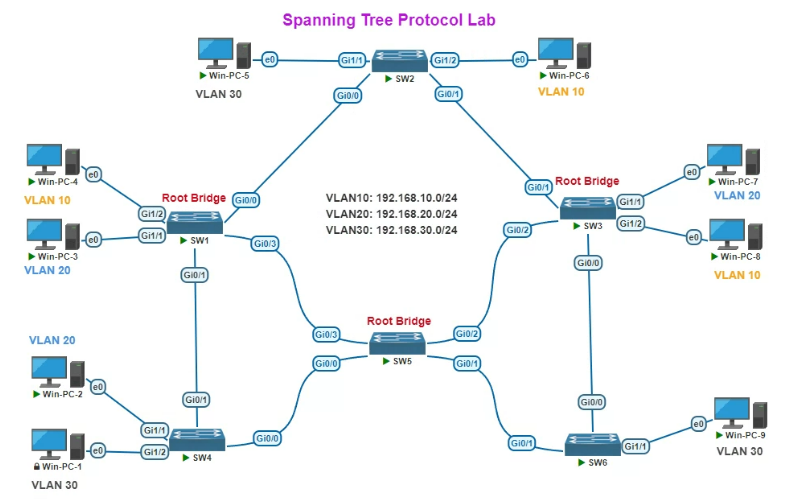
Table of ContentsHow Spanning Tree Protocol Actually WorksComparing STP, RSTP, MSTP, and PVSTConfiguring and Troubleshooting STP: Step by StepSpanning Tree Protocol Command Cheat SheetBringing It All Together Redundant links keep a switched network resilient — but without something managing them, those same redundant paths create loops that can bring a network down in seconds through broadcast storms and duplicate frames. Spanning Tree Protocol (STP) is the mechanism that makes redundancy safe. This guide covers how STP actually operates under the hood, how to choose between its modern variants, the exact commands to configure and troubleshoot it, and a ready-reference cheat sheet for day-to-day work. How Spanning Tree Protocol Actually Works Before touching a single configuration command, it helps to understand the election process and port states that let STP block loops without disconnecting anything permanently. Understand why loops are dangerous in the first place. A physical loop between switches causes broadcast frames to circulate endlessly, consuming bandwidth exponentially and eventually overwhelming switch CPUs and MAC address tables — this is why STP exists at all, even when redundant links are intentional and desirable. Learn how switches exchange BPDUs. Switches running STP send Bridge Protocol Data Units (BPDUs) out every port, containing information used to elect a root bridge and calculate the best path to it. BPDUs are exchanged continuously, not just once at startup, which lets STP react to topology changes. Understand root bridge election. Every switch in the STP domain compares Bridge IDs (a combination of a configurable priority value and the switch's MAC address) advertised in BPDUs, and the switch with the lowest Bridge ID becomes the root bridge — the logical center of the spanning tree that all other switches calculate their best path toward. See how non-root switches pick their best path. Each non-root switch determines its root port — the port with the lowest-cost path back to the root bridge — based on cumulative path cost (influenced by link speed) advertised in received BPDUs. Understand designated ports. On each network segment, the switch offering the lowest-cost path to the root becomes responsible for forwarding traffic on that segment, and its corresponding port becomes the designated port. Any other port on that same segment that isn't a root or designated port becomes a blocking port to prevent a loop. Learn the port states STP cycles through. A port moves through blocking, listening, learning, and finally forwarding states (in traditional 802.1D STP) before it's allowed to pass traffic — this staged progression is what traditionally makes STP convergence slow, since each transition includes a timed delay to avoid temporary loops during topology changes. Recognize how STP reacts to topology changes. If a link fails or a new one comes up, affected switches recalculate the tree — blocked ports may transition to forwarding once they're recalculated as the new best path, restoring connectivity automatically without manual intervention. With the underlying election and port-state mechanism clear, the practical question becomes which STP standard to actually run, since the original 802.1D design has been significantly improved upon since it was first standardized. Comparing STP, RSTP, MSTP, and PVST Multiple IEEE standards and vendor extensions have evolved from the original Spanning Tree Protocol, each addressing different limitations. Here's how they compare: Criteria STP (802.1D) RSTP (802.1w) MSTP (802.1s) PVST+ (Cisco) Convergence time Slow — 30-50 seconds after a topology change Fast — typically 1-2 seconds Fast — same rapid mechanism as RSTP Slow, matching underlying 802.1D timing unless combined with Rapid-PVST+ Spanning tree instances One instance for the entire network One instance for the entire network Multiple instances, each mapped to a group of VLANs One instance per VLAN Load balancing across VLANs Not supported Not supported Supported — different VLAN groups can use different paths Supported — each VLAN can have a different root bridge and active path Standard vs. proprietary IEEE standard (largely legacy) IEEE standard IEEE standard Cisco-proprietary (per-VLAN extension of 802.1D or, as Rapid-PVST+, of 802.1w) Configuration complexity Low Low Higher — requires MST region and instance-to-VLAN mapping Low, but scales with VLAN count since each VLAN runs its own instance Scalability (many VLANs) Poor fit — no per-VLAN awareness Poor fit — no per-VLAN awareness Strong — designed specifically for large VLAN counts Weaker at very large scale — CPU load grows with VLAN count Typical use today Rare in new deployments Common baseline in smaller networks Common in large enterprise campus networks Common in Cisco-only environments, usually as Rapid-PVST+ Best fit Legacy compatibility only Small-to-mid networks, simple topologies Large networks with many VLANs needing efficient link use Cisco shops wanting fast convergence with per-VLAN control without full MSTP complexity In practice, few networks run classic 802.1D STP today. The realistic choice is between Rapid-PVST+ (Cisco's default, giving fast per-VLAN convergence with minimal configuration) and MSTP (better suited once VLAN counts grow large enough that per-VLAN instances become inefficient to manage). Non-Cisco multi-vendor environments typically standardize on RSTP or MSTP directly, since PVST+ is Cisco-specific. Configuring and Troubleshooting STP: Step by Step With a variant chosen, here's the practical sequence for setting root bridge priority, hardening access ports with PortFast and BPDU Guard, and resolving the most common STP problems. Set the STP mode for your chosen variant. switch(config)# spanning-tree mode rapid-pvst Deliberately control root bridge election rather than leaving it to chance. Letting the root bridge be elected purely by lowest MAC address often puts it on the wrong (e.g., access-layer) switch — set priority explicitly on your intended core/distribution switch instead. switch(config)# spanning-tree vlan 10 priority 4096 Configure a secondary root bridge for redundancy. This ensures a predictable failover if your primary root bridge goes down, rather than a random re-election. switch(config)# spanning-tree vlan 10 root secondary Enable PortFast on end-device access ports only. PortFast skips the listening/learning delay for ports that will never connect to another switch, letting end devices get network access immediately instead of waiting 30+ seconds. switch(config-if)# spanning-tree portfast Enable BPDU Guard alongside PortFast. This protects against a device or rogue switch being plugged into a PortFast-enabled port and accidentally (or maliciously) participating in STP — the port is immediately disabled if a BPDU is received where none is expected. switch(config-if)# spanning-tree bpduguard enable Verify STP state and root bridge assignment. switch# show spanning-tree summary switch# show spanning-tree vlan 10 Troubleshoot a topology change flap — check for an unstable link first. Frequent topology change notifications (TCNs) usually point to a flapping physical link or a port going up and down repeatedly, not an STP misconfiguration itself. switch# show spanning-tree detail | include occurr|from Troubleshoot a suspected bridge loop — look for MAC address table instability. A classic symptom of an actual loop (versus a simple flap) is the same MAC address rapidly moving between different ports in the MAC address table, along with abnormally high CPU utilization. switch# show mac address-table | include <suspect-mac> Recover a port disabled by BPDU Guard. If BPDU Guard trips (typically because an unintended device or switch was connected to a PortFast port), the port needs to be manually re-enabled or configured for auto-recovery rather than resolving on its own. switch(config-if)# shutdown switch(config-if)# no shutdown Once root bridge placement is deliberate, PortFast and BPDU Guard are applied consistently across access ports, and TCN/flapping behavior is understood as a symptom to investigate rather than an STP failure itself, most day-to-day STP issues become quick to diagnose rather than mysterious. Spanning Tree Protocol Command Cheat Sheet For quick lookup during deployment or troubleshooting, here's a consolidated reference beyond what was already covered step-by-step above. # --- Mode selection --- # Classic Cisco PVST+ (802.1D per VLAN) switch(config)# spanning-tree mode pvst # Rapid-PVST+ (802.1w per VLAN) - common default switch(config)# spanning-tree mode rapid-pvst # MSTP (802.1s) switch(config)# spanning-tree mode mst # --- Root bridge control --- # Set explicit priority (lower = more likely root) switch(config)# spanning-tree vlan 10 priority 4096 # Auto-calculate priority to become root switch(config)# spanning-tree vlan 10 root primary # Auto-calculate priority as backup root switch(config)# spanning-tree vlan 10 root secondary # --- MSTP region and instance mapping --- switch(config)# spanning-tree mst configuration switch(config-mst)# name REGION1 switch(config-mst)# revision 1 switch(config-mst)# instance 1 vlan 10,20 # --- Port protection --- # Skip listening/learning on edge ports switch(config-if)# spanning-tree portfast # Disable port if unexpected BPDU received switch(config-if)# spanning-tree bpduguard enable # Prevent port from becoming root port switch(config-if)# spanning-tree guard root # Enable both globally on all PortFast ports switch(config)# spanning-tree portfast bpduguard default # --- Cost and timers --- # Manually set path cost on an interface switch(config-if)# spanning-tree cost 10 # Adjust BPDU hello interval (use cautiously) switch(config)# spanning-tree vlan 10 hello-time 2 # --- Verification --- # Overall STP mode and status switch# show spanning-tree summary # Detailed state for a specific VLAN switch# show spanning-tree vlan 10 # STP state for a specific interface switch# show spanning-tree interface gi1/0/1 # View MST region/instance mapping switch# show spanning-tree mst configuration # Verbose detail including TCN counts switch# show spanning-tree detail Keep this reference handy for moments when the concept is already clear and you just need the exact syntax — pair it with the verification commands from the walkthrough above to confirm any change actually took hold as intended. Bringing It All Together Spanning Tree Protocol makes sense once you see it as a continuous negotiation rather than a one-time setup: BPDUs elect a root bridge, port roles get assigned based on path cost, and the resulting tree adapts automatically whenever the topology changes. Choose Rapid-PVST+ or MSTP based on how many VLANs you're managing rather than defaulting to legacy STP, take deliberate control of root bridge placement instead of leaving it to chance, harden access ports with PortFast and BPDU Guard together, and keep the command reference above within reach for troubleshooting. Get those pieces right, and STP becomes one of the most reliable, "set it and forget it" protocols in your network rather than a recurring source of mysterious outages. -
- 254
- SPOTO
- 2026-07-30 14:06
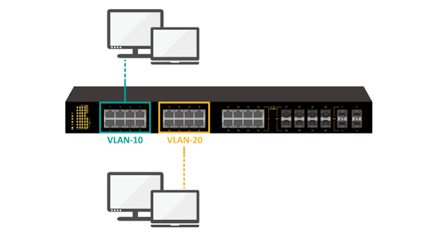
Table of ContentsHow VLAN Technology Works: Tagging, Broadcast Domains, and SegmentationComparing VLAN Types: Static, Dynamic, Voice, and Private VLANsConfiguring and Troubleshooting VLANs: Step by StepVLAN Configuration Command Cheat Sheet Across VendorsBringing It All Together VLANs are how a single physical switch infrastructure gets carved into multiple logical, isolated networks — and they're arguably the single most-used feature in enterprise switching after basic connectivity itself. This guide covers how VLAN tagging actually works under the hood, the different implementation types you can choose between, the exact steps to configure and troubleshoot them, and a ready-to-use command reference across the major switch vendors. How VLAN Technology Works: Tagging, Broadcast Domains, and Segmentation Before choosing a VLAN strategy or typing a single command, it's worth understanding the mechanism that makes VLANs possible in the first place. Start with the problem VLANs solve. Without VLANs, every device connected to a switch (or set of interconnected switches) shares a single broadcast domain — meaning broadcast traffic from any device reaches every other device. As networks grow, this becomes both a performance problem (broadcast traffic multiplies) and a security problem (every device can potentially see every other device's traffic). Understand logical segmentation. A VLAN (Virtual Local Area Network) creates a separate broadcast domain within the same physical switch or set of switches, without requiring separate physical hardware. Devices in different VLANs are isolated from each other at Layer 2 by default, even if they're plugged into the same physical switch. Learn how switches identify which VLAN a frame belongs to. On an access port (a port connecting directly to an end device), the switch simply tags incoming untagged frames with the VLAN configured on that port — the end device itself has no awareness that VLANs exist. Understand 802.1Q tagging for inter-switch links. When traffic for multiple VLANs needs to travel between switches over a single physical link (a trunk), the 802.1Q standard inserts a 4-byte tag into the Ethernet frame header identifying which VLAN the frame belongs to. The receiving switch reads this tag to know which VLAN's broadcast domain the frame should stay within, then strips the tag again before delivering it to an access port. Recognize the native VLAN exception. On a trunk port, one VLAN can be designated as the "native" VLAN — frames belonging to it are sent untagged rather than with an 802.1Q tag. This exists mostly for backward compatibility with older equipment, but it's also a common source of misconfiguration if both ends of a trunk don't agree on which VLAN is native. See how VLANs enable both isolation and controlled communication. Devices within the same VLAN communicate freely at Layer 2. Communication between VLANs requires Layer 3 routing (via a router or a Layer 3 switch with inter-VLAN routing configured), which gives network administrators a deliberate control point for applying security policy between segments. With the underlying tagging mechanism clear, the next question is which VLAN assignment strategy fits your environment — and that's where the different implementation types come in. Comparing VLAN Types: Static, Dynamic, Voice, and Private VLANs Not all VLANs are assigned the same way. Here's how the major implementation types stack up against each other: Criteria Static (Port-Based) VLAN Dynamic VLAN (802.1X-based) Voice VLAN Private VLAN Assignment method Manually configured per switch port Assigned dynamically based on device/user authentication (via RADIUS/802.1X) Configured on a port to carry both a device's voice and data traffic on separate VLANs A VLAN subdivided into isolated sub-groups within the same broadcast domain Configuration effort Low — one command per port Higher — requires RADIUS server integration and 802.1X supplicant configuration Low — a dedicated command alongside the data VLAN on the same port Moderate — requires defining primary and secondary (isolated/community) VLANs Flexibility for mobile users Low — moving to a different port requires reconfiguration High — the correct VLAN follows the authenticated user/device to whatever port they connect on N/A — designed for a fixed voice device (e.g., IP phone) alongside a PC Low — designed for fixed segmentation, not user mobility Typical use case Most general-purpose wired ports in a stable environment BYOD environments, hot-desking, environments needing identity-based network access control Ports serving an IP phone with a daisy-chained PC behind it Hosting/data center environments needing device isolation within a shared subnet Isolation granularity Whole VLAN (broadcast domain) Whole VLAN, but assignment is identity-driven rather than port-driven Separates voice and data traffic onto distinct VLANs on the same physical port Sub-VLAN granularity — devices can be isolated from each other even within the same VLAN Management overhead Low, but scales poorly with frequent device moves Higher upfront (RADIUS setup), lower ongoing (no manual reconfiguration needed) Low Moderate — more moving parts to document and troubleshoot Best fit Stable desks, servers, fixed infrastructure Environments with frequent device/user movement or strict access control needs Any port combining an IP phone and a PC Multi-tenant or shared-subnet environments needing device-to-device isolation Most enterprise networks default to static VLANs for the bulk of fixed infrastructure, layer in voice VLANs wherever IP phones are deployed, and reserve dynamic (802.1X-based) VLANs or private VLANs for the specific use cases — mobility and multi-tenant isolation, respectively — where their added complexity is actually justified. Configuring and Troubleshooting VLANs: Step by Step With a VLAN strategy chosen, here's the practical sequence for setting up access ports, trunk ports, and resolving the most common issues that come up afterward. Commands below use Cisco-style syntax. Create the VLAN(s) on the switch. switch(config)# vlan 10 switch(config-vlan)# name SALES switch(config)# vlan 20 switch(config-vlan)# name VOICE Assign an access port to a VLAN. switch(config)# interface gigabitEthernet 1/0/5 switch(config-if)# switchport mode access switch(config-if)# switchport access vlan 10 Add a voice VLAN to the same port if an IP phone is present. switch(config-if)# switchport voice vlan 20 Configure a trunk port between switches. switch(config)# interface gigabitEthernet 1/0/48 switch(config-if)# switchport trunk encapsulation dot1q switch(config-if)# switchport mode trunk switch(config-if)# switchport trunk allowed vlan 10,20 switch(config-if)# switchport trunk native vlan 99 Verify VLAN and port assignments. switch# show vlan brief switch# show interfaces gigabitEthernet 1/0/5 switchport Troubleshoot a device that can't communicate — check VLAN assignment first. Confirm the port is in the VLAN you expect using the verification command above; a surprising number of "network down" tickets trace back to a port sitting in the wrong (often default) VLAN. Troubleshoot cross-switch connectivity issues — check trunk configuration next. Confirm both ends of the trunk allow the same VLANs and agree on the native VLAN. switch# show interfaces trunk A native VLAN mismatch between the two ends is one of the most common causes of intermittent or one-way connectivity across a trunk link. Troubleshoot inter-VLAN communication issues — check Layer 3 routing. If devices in different VLANs can't reach each other, confirm a Layer 3 device (router or Layer 3 switch) has an interface (or SVI) in each relevant VLAN with correct IP addressing. switch(config)# interface vlan 10 switch(config-if)# ip address 10.10.10.1 255.255.255.0 Confirm end-to-end reachability after making changes. Use basic connectivity testing from an affected device, and re-check the VLAN/trunk verification commands above if the issue persists — most VLAN problems resolve once assignment, trunk configuration, and routing are all confirmed to agree with each other. Once ports are correctly assigned, trunks agree on allowed and native VLANs, and Layer 3 routing exists where needed, VLAN-related issues become rare — most ongoing work at this layer is simply adding new VLANs or ports rather than re-troubleshooting the fundamentals. VLAN Configuration Command Cheat Sheet Across Vendors For quick reference during deployment or troubleshooting, here's a consolidated command set — Cisco IOS commands are shown in full, with HP/HPE (Comware and ProVision) equivalents noted alongside where syntax diverges meaningfully. # --- Create and name a VLAN --- # Cisco: switch(config)# vlan 10 switch(config-vlan)# name SALES # HP Comware: <HP> system-view [HP] vlan 10 [HP-vlan10] name SALES # HP ProVision: switch(config)# vlan 10 switch(vlan-10)# name SALES # --- Assign an access port --- # Cisco: switch(config-if)# switchport mode access switch(config-if)# switchport access vlan 10 # HP Comware: [HP-GigabitEthernet1/0/1] port link-type access [HP-GigabitEthernet1/0/1] port default vlan 10 # HP ProVision: switch(config)# vlan 10 switch(vlan-10)# untagged 1 # --- Configure a trunk port --- # Cisco: switch(config-if)# switchport mode trunk switch(config-if)# switchport trunk allowed vlan 10,20 # HP Comware: [HP-GigabitEthernet1/0/48] port link-type trunk [HP-GigabitEthernet1/0/48] port trunk permit vlan 10 20 # HP ProVision: switch(config)# vlan 10 switch(vlan-10)# tagged 48 # --- Voice VLAN --- # Cisco: switch(config-if)# switchport voice vlan 20 # --- Verification (Cisco) --- switch# show vlan brief switch# show interfaces trunk switch# show interfaces status # --- Verification (HP Comware) --- <HP> display vlan <HP> display interface brief # --- Verification (HP ProVision) --- switch# show vlans switch# show vlans port 1 Keep this section bookmarked as your quick-lookup reference once you already understand the "why" from the configuration walkthrough above — it's built to be copy-pasted, not re-explained each time. Bringing It All Together VLAN technology is straightforward once the pieces click into place: 802.1Q tagging is what lets one physical link carry multiple isolated broadcast domains, the type of VLAN you choose (static, dynamic, voice, or private) depends on whether your priority is simplicity, user mobility, phone deployment, or tenant isolation, and the vast majority of real-world VLAN problems trace back to a port in the wrong VLAN or a trunk disagreement between two switches. Get the tagging concept solid, pick the right VLAN type for each use case rather than defaulting to one everywhere, and keep the command reference above close at hand — that combination covers nearly every VLAN scenario you'll run into. -
- 310
- SPOTO
- 2026-07-30 14:02
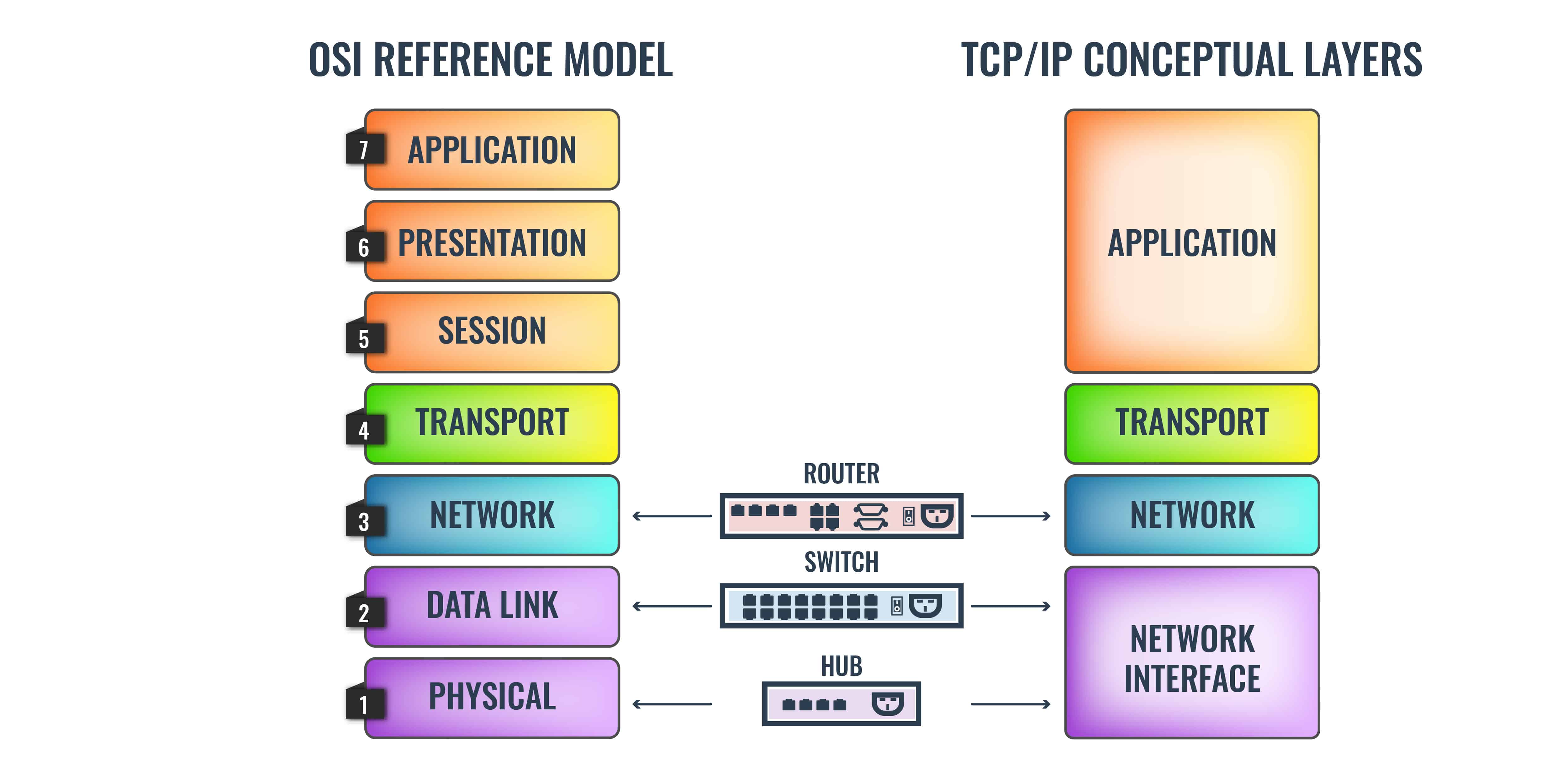
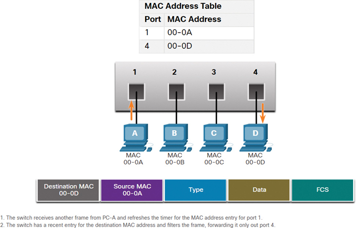
Table of ContentsThe Core Layer 2 Protocols Every Switch Relies OnComparing STP, RSTP, and MSTP for Loop PreventionConfiguring VLAN Trunking and LACP: Step-by-StepLayer 2 Protocol Command Cheat SheetBringing It All Together Every switched network runs on a handful of Layer 2 protocols working quietly in the background — protocols that prevent loops, negotiate trunk links, bundle redundant connections, and let devices discover their neighbors automatically. Understanding what each one does, how the different loop-prevention variants compare, and exactly which commands bring them to life on a real switch is the difference between a network that just works and one that mysteriously breaks the moment you add a second uplink. This guide covers all of it, from concepts through to a ready-reference command sheet. The Core Layer 2 Protocols Every Switch Relies On Before configuring anything, it helps to know what each of these protocols is actually responsible for and how they interact with one another. Spanning Tree Protocol (STP) — loop prevention. Whenever switches are connected with redundant links (for resilience), those links create physical loops that would otherwise cause broadcast storms. STP solves this by electing a root bridge and selectively blocking redundant paths, keeping exactly one active path between any two switches while holding the rest in standby. VLAN Trunking Protocol (VTP) — VLAN database synchronization. In multi-switch environments, VTP lets one switch act as a "server" that propagates VLAN configuration to other switches configured as "clients," so you don't have to manually recreate every VLAN on every switch in the network. Link Aggregation Control Protocol (LACP) — bundling redundant links. Rather than letting STP block a redundant physical link entirely, LACP bundles multiple physical links into a single logical link (an EtherChannel or port channel), giving you both increased bandwidth and redundancy without wasting capacity. Link Layer Discovery Protocol (LLDP) and Cisco Discovery Protocol (CDP) — neighbor discovery. These vendor-neutral (LLDP) and Cisco-proprietary (CDP) protocols let directly connected devices exchange information about themselves — device type, capabilities, port ID — which is invaluable for mapping out a network or troubleshooting physical connectivity without needing existing documentation. How they work together in practice. A typical switch uplink runs LACP to bundle physical links into one logical trunk, that trunk carries 802.1Q-tagged traffic for multiple VLANs (kept in sync across switches via VTP), STP runs underneath to make sure no unintended loop exists outside the bundled link, and LLDP/CDP quietly report neighbor information the whole time for visibility. None of these protocols replace each other — they solve different problems at the same layer. With the roles of each protocol clear, the next natural question is which loop-prevention variant to actually deploy, since STP itself has evolved considerably since its original design. Comparing STP, RSTP, and MSTP for Loop Prevention Spanning Tree Protocol has gone through multiple revisions, and picking the right variant depends heavily on your topology size and convergence requirements. Criteria STP (802.1D) RSTP (802.1w) MSTP (802.1s) Convergence time Slow — up to 30-50 seconds after a topology change Fast — typically under 1-2 seconds Fast — same rapid convergence as RSTP VLAN handling One spanning tree instance for the entire network (or per-VLAN with proprietary extensions) One spanning tree instance for the entire network by default Multiple instances, each mapped to a group of VLANs Best for Legacy networks with minimal redundancy changes; largely superseded today Small to mid-sized networks with a single or few VLANs Larger networks with many VLANs needing load balancing across redundant links Load balancing across links Not supported — one active path for the whole network Not supported — one active path for the whole network Supported — different VLAN groups can use different active paths Configuration complexity Low Low Higher — requires defining MST instances and VLAN-to-instance mapping Backward compatibility N/A (the original standard) Compatible with legacy STP switches (falls back automatically) Compatible with RSTP; requires matching MST region config to interoperate fully with other MSTP switches Typical use case today Rare in new deployments Small offices, simple topologies, or a starting point before MSTP Enterprise campus networks with many VLANs and a need for efficient link utilization The practical guidance: RSTP is the sensible default for most straightforward networks today, since it's simple to configure and converges quickly; reach for MSTP specifically when you have enough VLANs that spreading load across multiple redundant paths meaningfully improves bandwidth utilization, and you're prepared to manage the added instance-mapping complexity that comes with it. Configuring VLAN Trunking and LACP: Step-by-Step With the concepts and STP variant decided, here's how to actually bring 802.1Q trunking and LACP link aggregation to life on a Cisco-style switch. Configure the physical interfaces that will form your bundle. Before enabling LACP, make sure the member ports have matching speed, duplex, and VLAN settings — mismatches here are the most common cause of a bundle failing to form. switch(config)# interface range gigabitEthernet 1/0/1-2 switch(config-if-range)# shutdown Enable LACP on the member interfaces. Use active mode so the switch initiates negotiation rather than waiting passively (use active on at least one side of the connection). switch(config-if-range)# channel-group 1 mode active Verify the port channel interface was created. switch(config-if-range)# no shutdown switch# show etherchannel summary Configure the resulting port-channel interface as an 802.1Q trunk. Once the physical interfaces are bundled, you configure trunking on the logical port-channel interface — not on the individual member ports. switch(config)# interface port-channel 1 switch(config-if)# switchport trunk encapsulation dot1q switch(config-if)# switchport mode trunk Restrict the trunk to only the VLANs it should actually carry. Allowing every VLAN by default is a common security and stability oversight — explicitly list only what's needed. switch(config-if)# switchport trunk allowed vlan 10,20,30 Set a native VLAN for untagged traffic. Make sure both ends of the trunk agree on the native VLAN — a mismatch here is a classic misconfiguration that silently leaks traffic between VLANs. switch(config-if)# switchport trunk native vlan 99 Verify the trunk and LACP bundle are both healthy. switch# show interfaces trunk switch# show etherchannel port-channel switch# show lacp neighbor Confirm STP sees the port-channel as expected. Since the bundle is a single logical interface, STP treats it as one link — check that it's forwarding, not blocking, on the interface you expect. switch# show spanning-tree interface port-channel 1 Once you've verified trunking, LACP bundling, and STP state all agree with each other, the logical link is functioning as intended — bandwidth is aggregated, VLANs are correctly tagged, and the whole bundle appears to STP as a single resilient path rather than multiple separate links it might otherwise block. Layer 2 Protocol Command Cheat Sheet For quick lookup during day-to-day work or troubleshooting, here's a consolidated reference covering the protocols discussed above plus VTP and neighbor discovery, beyond what was already configured step-by-step in the previous section. # --- Spanning Tree Protocol --- switch(config)# spanning-tree mode rapid-pvst # Enable RSTP (per-VLAN) switch(config)# spanning-tree mode mst # Enable MSTP switch(config)# spanning-tree vlan 10 priority 4096 # Influence root bridge election switch# show spanning-tree summary # Verify STP mode and status switch# show spanning-tree vlan 10 # View STP state for a VLAN switch# show spanning-tree mst configuration # View MST region/instance mapping # --- VLAN Trunking Protocol --- switch(config)# vtp mode server # Set switch as VTP server switch(config)# vtp mode client # Set switch as VTP client switch(config)# vtp domain CORP # Set VTP domain name switch(config)# vtp password S3cr3t # Set VTP authentication password switch# show vtp status # Verify VTP mode/domain/revision # --- LACP / EtherChannel --- switch(config-if)# channel-group 1 mode active # Enable LACP (active) switch(config-if)# channel-group 1 mode passive # Enable LACP (passive) switch# show etherchannel summary # View all port-channel bundles switch# show lacp counters # View LACP packet counters # --- LLDP --- switch(config)# lldp run # Enable LLDP globally switch# show lldp neighbors # View discovered neighbors switch# show lldp neighbors detail # Detailed neighbor info # --- CDP (Cisco-only) --- switch(config)# cdp run # Enable CDP globally switch(config-if)# cdp enable # Enable CDP per interface switch# show cdp neighbors # View discovered neighbors switch# show cdp neighbors detail # Detailed neighbor info # --- General troubleshooting --- switch# show interfaces status # Quick port/VLAN/duplex overview switch# show interfaces trunk # Trunk state and allowed VLANs Bookmark this section specifically for moments when you already understand the concept and just need the exact syntax — pair it with the verification commands from the configuration walkthrough above when you need to confirm a change actually took effect. Bringing It All Together Layer 2 protocols are easiest to reason about once you see them as a stack of cooperating layers rather than isolated features: STP (or its faster RSTP/MSTP variants) keeps the topology loop-free, LACP reclaims bandwidth that STP would otherwise block, VLAN trunking and VTP keep segmentation consistent across switches, and LLDP/CDP give you visibility into how it's all physically connected. Start with the right STP variant for your topology size, configure trunking and LACP together rather than as separate afterthoughts, and keep the command cheat sheet handy for the inevitable 2 a.m. troubleshooting session — that combination covers the vast majority of real-world Layer 2 work. -
- 317
- SPOTO
- 2026-07-30 11:08
Table of ContentsHow Switches Learn MAC Addresses in the First PlaceStatic vs. Dynamic MAC Entries: Which Should You Use?MAC Address Table CLI Commands: A Quick-Reference Cheat SheetClearing or Flushing the MAC Address Table Without a RebootProtecting the MAC Address Table from Flooding AttacksBringing It All Together Every Ethernet switch relies on a single, deceptively simple data structure to do its job: the MAC address table (also called the CAM table, for Content Addressable Memory). Get comfortable with how it learns addresses, how to view and manipulate it from the CLI, and how to lock it down against attack, and you'll have covered one of the most fundamental — and most exploitable — pieces of switching behavior. This guide walks through the full picture, from the underlying mechanism to the security hardening that protects it. How Switches Learn MAC Addresses in the First Place Before you can manage a MAC address table, it helps to understand exactly how a switch builds one without any manual configuration at all. A frame arrives on a port. When a switch receives an Ethernet frame, it examines the frame's source MAC address — this is the address of the device that sent it, not the destination. The switch records the source address and port. It creates (or refreshes) an entry in the MAC address table mapping that source MAC address to the physical port the frame arrived on. This is the "learning" part of the process, and it happens continuously and automatically for every frame received. The switch checks the destination address against the table. Next, it looks at the frame's destination MAC address and checks whether that address already exists in the table. Known destination → the switch forwards, it doesn't flood. If the destination MAC is already in the table, the switch forwards the frame only out the specific port associated with that address — this is what makes switching more efficient than old-style hub-based flooding. Unknown destination → the switch floods. If the destination MAC isn't yet in the table (common early in a connection, or for a device that rarely transmits), the switch floods the frame out every port in the same VLAN except the one it arrived on. Whichever device actually owns that address responds, and the switch learns its location from that reply. Entries age out over time. Dynamically learned entries aren't permanent — each has an aging timer (300 seconds/5 minutes is the common default) that resets every time a frame is seen from that source address. If no traffic arrives from a MAC address before its timer expires, the entry is removed to keep the table from filling with stale data. The table adapts automatically to topology changes. If a device moves to a different port (or its NIC changes), the switch simply relearns the new source-port mapping the next time that device transmits — no manual intervention needed under normal operation. This self-learning behavior is what makes switches "plug and play" for basic connectivity — but it's also exactly the mechanism attackers try to exploit, which is why the security section later in this guide matters just as much as the mechanics above. Static vs. Dynamic MAC Entries: Which Should You Use? Once you understand how dynamic learning works, the next practical question is whether you should ever override it with manually configured static entries. Here's how the two approaches compare: Criteria Dynamic Entries Static Entries Configuration effort None — learned automatically Manual entry per device, per port Scalability Scales effortlessly to thousands of devices Impractical beyond a small number of critical devices Adapts to device moves Yes — relearns automatically No — must be manually updated if device moves Table stability Entries age out and get relearned continuously Entries never age out or get removed automatically Security posture Vulnerable to MAC flooding without additional protections Immune to flooding-based table exhaustion for those specific entries Best use case General end-user ports, guest devices, most of the network Critical infrastructure: servers, network management stations, security cameras with fixed ports Management overhead Low Grows linearly with number of static entries Risk if misconfigured Low — self-correcting Can cause connectivity issues if a device's actual MAC or port changes and the static entry isn't updated In practice, most networks run almost entirely on dynamic learning and reserve static entries for a small handful of high-value, rarely-moved devices — pairing static entries for critical infrastructure with the port security features covered later gives you the stability benefits without the full management burden of static entries everywhere. MAC Address Table CLI Commands: A Quick-Reference Cheat Sheet With the concepts and trade-offs covered, here are the exact commands you'll reach for most often when working with a MAC address table (Cisco IOS syntax shown; most other vendors follow a very similar pattern). # View the entire MAC address table switch# show mac address-table # View MAC entries learned on a specific interface switch# show mac address-table interface gigabitEthernet 1/0/1 # View MAC entries for a specific VLAN switch# show mac address-table vlan 10 # View only dynamically learned entries switch# show mac address-table dynamic # View only statically configured entries switch# show mac address-table static # Count total MAC addresses in the table switch# show mac address-table count # Configure a static MAC address entry (bind MAC to a port/VLAN) switch(config)# mac address-table static 0011.2233.4455 vlan 10 interface gigabitEthernet 1/0/5 # Remove a specific static MAC entry switch(config)# no mac address-table static 0011.2233.4455 vlan 10 interface gigabitEthernet 1/0/5 # Change the aging time for dynamic entries (in seconds) switch(config)# mac address-table aging-time 600 # Disable aging entirely for a VLAN (use with caution) switch(config)# mac address-table aging-time 0 vlan 10 Keep this list handy for day-to-day troubleshooting — but note that clearing entries (covered next) uses a different command family entirely from viewing or configuring them. Clearing or Flushing the MAC Address Table Without a Reboot Sometimes you need to force the table to relearn from scratch — after a topology change, a suspected stale entry, or during troubleshooting — without rebooting the switch. Here's how to do it across the most common platforms. Identify why you need to clear the table. Common triggers include a device that moved ports but the switch hasn't relearned yet (before the aging timer naturally expires), suspected MAC spoofing, or verifying that a fix actually resolved a Layer 2 loop or duplicate-MAC issue. On Cisco switches, clear the entire dynamic table. switch# clear mac address-table dynamic On Cisco switches, clear entries for a specific interface only. switch# clear mac address-table dynamic interface gigabitEthernet 1/0/1 On Cisco switches, clear entries for a specific VLAN only. switch# clear mac address-table dynamic vlan 10 On HP/HPE (Comware or ProVision) switches, use the equivalent flush command. switch# clear mac-address (Comware-based switches use reset mac-address-table dynamic instead — check your specific platform family, since HP's syntax varies between ProVision and Comware OS.) On Huawei switches, use the reset command. <Huawei> reset mac-address dynamic Verify the clear operation worked. Immediately after clearing, run the show/display mac-address equivalent for your platform — the table should show a sharp drop in entries, which then repopulate naturally as traffic resumes. Expect a brief flooding period after clearing. Right after a flush, the switch has no dynamic entries, so it will flood unicast frames to unknown destinations until it relearns — this is normal and typically resolves within seconds on an active network. Clearing the table is a safe, non-disruptive operation on its own — the brief flooding period is a normal side effect, not a sign something went wrong. Protecting the MAC Address Table from Flooding Attacks The dynamic learning behavior covered earlier has an exploitable weakness: an attacker can flood a switch with frames using thousands of fake source MAC addresses, filling the table's finite capacity. Once full, many switches fail open — flooding all traffic to all ports like a hub, which lets an attacker on any port sniff traffic meant for other devices. Port security is the primary defense. Enable port security on access ports. This is the foundational step — port security restricts how many and which MAC addresses are allowed to be learned on a given port. switch(config)# interface gigabitEthernet 1/0/1 switch(config-if)# switchport mode access switch(config-if)# switchport port-security Set a maximum number of allowed MAC addresses per port. For a typical end-user port with a single device, one is usually sufficient; adjust upward for ports feeding an IP phone plus a PC. switch(config-if)# switchport port-security maximum 2 Choose a violation action. This determines what happens when the maximum is exceeded — protect (drop offending traffic silently), restrict (drop and log/increment a counter), or shutdown (err-disable the port entirely, the most secure but most disruptive default). switch(config-if)# switchport port-security violation restrict Decide between sticky and fully static learning. "Sticky" learning lets the switch dynamically learn the first allowed MAC address(es) and then convert them to static entries automatically — a good middle ground between manual effort and security. switch(config-if)# switchport port-security mac-address sticky Set an aging time for port-security entries if needed. This allows legitimate device changes (like a laptop swap) to be accommodated without manual intervention, while still capping the number of simultaneous addresses. switch(config-if)# switchport port-security aging time 60 switch(config-if)# switchport port-security aging type inactivity Verify port security status and violation counts. switch# show port-security interface gigabitEthernet 1/0/1 switch# show port-security address Recover an err-disabled port after a violation. If you used the shutdown violation action and a port trips, it needs to be manually re-enabled (or configured for auto-recovery) rather than clearing on its own. switch(config)# interface gigabitEthernet 1/0/1 switch(config-if)# shutdown switch(config-if)# no shutdown Layer in additional protections for high-risk environments. Beyond port security, features like DHCP snooping and Dynamic ARP Inspection complement MAC-table protection by addressing related spoofing vectors that port security alone doesn't cover. Port security turns the switch's biggest structural weakness — unlimited automatic learning — into a bounded, monitored process, which is the difference between a MAC flooding attempt failing quietly and one that takes down visibility across an entire VLAN. Bringing It All Together The MAC address table is one of those pieces of networking infrastructure that works invisibly until something goes wrong — a device that won't reconnect after a move, a suspicious flood of unknown traffic, or a switch behaving like a hub during an attack. Understanding the learning mechanism covered at the start of this guide makes the rest fall into place naturally: you'll know when static entries are worth the management overhead, which commands to reach for during day-to-day work or troubleshooting, and why port security isn't optional hardening but a direct countermeasure to how the table itself is built. Master these fundamentals, and MAC-table issues go from mysterious to routine. -
- 648
- SPOTO 2
- 2026-07-14 10:18
Table of ContentsWeeks 1–3: The Core Fundamentals and Addressing Muscle MemoryWeeks 4–6: Building the Local Access Fabric and Routing DataWeeks 7–9: Essential IP Services, Infrastructure Security, and Edge GatewaysWeeks 10–11: Automation, JSON Formatting, and Practical AI ToolsWeek 12: The Final Review and Realistic Exam Simulations With all the talk about cloud computing and automation, some people thought traditional networking certifications were losing their value. Cisco put that rumor to rest with the release of the CCNA 200-301 Version 2.0 blueprint. This update makes it clear that solid routing, switching, and core troubleshooting skills are still the bedrock of any IT career. Whether you want to clear the exam under the current format or prepare yourself for the upcoming v2.0 updates, trying to wing it won't work. You need a structured, step-by-step approach to cover this amount of technical material. This 12-week study plan breaks the syllabus down into manageable weekly targets, focusing on what you actually need to know to pass. Weeks 1–3: The Core Fundamentals and Addressing Muscle Memory The first three weeks are all about the building blocks. If your foundational knowledge is shaky, advanced routing and security configurations will make no sense later on. Week 1: Cabling, Interfaces, and Hardware Realities Start by learning how data moves across physical media. You need to know the distance limits and speed capabilities of fiber-optic and copper cables. More importantly, focus on the command-line interface (CLI). Get used to running the show interfaces command and interpreting the output. You should be able to instantly spot physical-layer issues like duplex mismatches, runts, giants, and CRC errors. Wrap up the week by learning how virtual machines and containers fit into modern data centers. Weeks 2–3: IPv4 Subnetting, VLSM, and IPv6 Basics Subnetting cannot just be something you "kind of" understand; it has to become second nature. You should be able to look at an IP address with a CIDR notation and figure out the network ID, broadcast address, and total usable hosts in less than thirty seconds. IPv4 Practice: Work on Variable Length Subnet Masking (VLSM) scenarios. Practice configuring static IPs, default gateways, and DHCP relay agents on a router. IPv6 Transition: Learn the anatomy of an IPv6 address. Focus on how link-local addresses work, how global unicast addresses are assigned, and how EUI-64 uses a MAC address to create an interface ID. Weeks 4–6: Building the Local Access Fabric and Routing Data Now that you can address a network, it is time to connect the pieces and control how traffic flows between them. Week 4: VLANs, Trunks, and EtherChannels Switches keep local traffic organized. Spend this week learning how to create VLANs and isolate broadcast domains. Practice setting up 802.1Q trunk links between switches, and make sure you understand why native VLAN mismatches cause security and connectivity issues. Before the week ends, combine multiple physical links into a single logical connection by configuring EtherChannels using Link Aggregation Control Protocol (LACP). Week 5: Spanning Tree Protocol and Network Discovery Redundant links prevent network downtime, but they also cause catastrophic switching loops. Learn how the Spanning Tree Protocol (STP) and Rapid STP (802.1w) prevent this by electing a root bridge and blocking specific ports. You need to know how to manually change bridge priorities to keep traffic paths predictable. Finally, turn on Cisco Discovery Protocol (CDP) and Link Layer Discovery Protocol (LLDP) to map out connected neighbors. Week 6: The Mechanics of Routing and OSPFv2 Shift your focus to Layer 3. You must understand the "packet walk"—how routers strip off Layer 2 frames, read Layer 3 IP headers, and rebuild new frames to send data to the next hop. Learn the difference between static routes, floating static routes, and dynamic routing. Then, dive into Single-Area OSPFv2. You need to know the OSPF neighbor states and, more importantly, how to troubleshoot a broken adjacency when hello timers, subnets, or authentication keys do not match. Weeks 7–9: Essential IP Services, Infrastructure Security, and Edge Gateways Networks need to be secure, and they need to provide services to the endpoints connected to them. Week 7: NAT, PAT, and Domain Name Resolution The internet runs out of public IPv4 addresses daily, which is why Network Address Translation (NAT) is everywhere. Practice configuring static NAT, dynamic NAT pools, and Port Address Translation (PAT/Overload). Once your edge router can talk to the internet, look into Domain Name System (DNS) configurations. Learn how a client resolves names to IPs and understand the roles of basic resource records like A, AAAA, and CNAME. Week 8: Access Control Lists and Switch Port Security Security starts at the perimeter and extends down to the individual switch port. Spend this week writing and applying standard and extended Access Control Lists (ACLs) to filter traffic based on source, destination, and port numbers. Next, protect your local switches by configuring Port Security to limit access to approved MAC addresses. Turn on DHCP Snooping and Dynamic ARP Inspection (DAI) to stop common network attacks like rogue DHCP servers Week 9: Device Management and Remote Access Architects Learn how to securely manage your network gear. Set up Secure Shell (SSH) access, disable unencrypted Telnet, and configure local AAA (Authentication, Authorization, and Accounting) protocols. To finish the architecture block, review how site-to-site IPsec VPNs differ from remote-access solutions, and study the basic design of cloud-managed networks and traditional three-tier enterprise architectures. Weeks 10–11: Automation, JSON Formatting, and Practical AI Tools The modern CCNA requires comfort with software-defined concepts and automated workflows. Week 10: Programmatic Fabric and REST APIs Network management has evolved past configuring one box at a time. Learn how central controllers talk to network devices by separating the control plane from the data plane. Practice reading and parsing JavaScript Object Notation (JSON) scripts. You need to understand how REST APIs use standard HTTP verbs—GET, POST, PUT, and DELETE—to push configuration changes, and learn what configuration management tools like Ansible do at a high level. Week 11: Network Operations and AI Integration See how AI tools are actually used by network admins. Practice writing effective prompts for generative AI models to help you audit configuration files, decipher long error logs, or write basic automation scripts. Study how predictive analytics and standard SNMP monitoring work together to alert you about hardware issues before a link completely fails. Week 12: The Final Review and Realistic Exam Simulations The last week is entirely about test-taking strategy and refining your pacing. Week 12: Performance Sprints and Time Management Cisco's exam environment can be challenging. You cannot use a "back button" to return to a skipped question, and the grading engine gives zero partial credit for multi-select items or practical lab simulations. Use this week to take full-length, timed practice tests. Pay close attention to how long it takes you to parse routing tables and debug broken configs. Use your practice scores to find your remaining weak areas and review those specific commands until you have absolute clarity. Getting Past the Finish Line To make this 12-week schedule work, passive reading is not enough. You need to spend time configuring topologies and seeing what happens when things break. Developing that real-world command-line familiarity is what gets you through the time limits of the actual exam. When you are ready to test your knowledge against realistic questions, using structured mock exams can make a huge difference. SPOTO offers updated CCNA practice question pools and exam simulators built to mimic the exact style, scenario logic, and multi-select formats used by Cisco. Testing yourself in these realistic environments helps you find your blind spots early, refine your pacing, and walk into the testing center with the confidence to pass on your first try.