





TRUSTED BY THE SMARTEST TEAMS IN THE WORLD FOR CERTIFIED CANDIDATES
SPOTO Blogs
Useful learning materials to become certified IT personnel
-
- 494
- SPOTO
- 2026-07-31 15:39
-
- 411
- SPOTO
- 2026-07-31 15:30
-
- 433
- SPOTO
- 2026-07-31 15:24
-
- 486
- SPOTO
- 2026-07-31 15:16
-
- 747
- SPOTO
- 2026-07-31 15:09
-
- 413
- SPOTO
- 2026-07-31 14:58
-
- 562
- SPOTO
- 2026-07-31 14:51
-
- 382
- SPOTO
- 2026-07-31 14:45
-
- 890
- SPOTO 2
- 2026-07-31 10:50

TRUSTED BY THE SMARTEST TEAMS IN THE WORLD FOR CERTIFIED CANDIDATES
SPOTO Blogs
Useful learning materials to become certified IT personnel
-
- 494
- SPOTO
- 2026-07-31 15:39
Table of ContentsUnderstanding the Cisco Automation Certification PathComparing Cisco Automation Certification LevelsHow to Study for Cisco Automation Certification With No Coding Background Network automation skills have moved from "nice to have" to a baseline expectation for network engineers, and Cisco's certification track reflects that shift. In February 2026, Cisco renamed its entire DevNet certification line to Cisco Automation certifications — same exams, same content, but now folded into the familiar CCNA/CCNP/CCIE naming structure. If you're planning your first automation certification, this guide walks through the full path and prerequisites, compares the certification levels so you can pick the right target, points you to legitimate study resources for the exam, and lays out a study strategy specifically for engineers coming from a traditional networking background with little or no coding experience. Understanding the Cisco Automation Certification Path Cisco's automation track — formerly branded DevNet, now Cisco Automation — validates the ability to build software, use APIs, and automate infrastructure on top of Cisco platforms. It sits alongside Cisco's traditional CCNA/CCNP/CCIE tracks rather than replacing them, and the certifications you may have earned as "DevNet Associate," "DevNet Professional," or "DevNet Expert" were automatically migrated to their new names with no need to retake anything. Here's how the path is structured, from entry point to expert level: Start with CCNA Automation (formerly DevNet Associate), exam 200-901 DEVASC. This is the entry-level credential and has no formal prerequisites, though Cisco recommends around 12 months of hands-on software development experience, including basic Python. It's designed for engineers who are new to automation and covers software development fundamentals, working with APIs, application deployment, and infrastructure automation basics alongside core network fundamentals. Build foundational skills before attempting the exam. Comfort with Python fundamentals (data types, loops, functions), a basic understanding of REST APIs and JSON, and familiarity with core networking concepts (which most traditional network engineers already have) will make the associate-level material far more approachable. Progress to CCNP Automation (formerly DevNet Professional) once you have real automation experience under your belt. This professional-level certification goes deeper into software design, application security, infrastructure as code, and automating across multiple Cisco platforms, and it assumes working familiarity with the concepts validated at the associate level. Aim for CCIE Automation (formerly DevNet Expert) at the top of the track, which requires passing a rigorous hands-on lab exam demonstrating the ability to design, build, secure, and troubleshoot automated solutions across complex, multi-platform environments. Choose concentration exams where relevant, since the professional level allows some flexibility in which platform-focused topics you specialize in, similar to how CCNP tracks work on the networking side. With the overall path in view, the next practical question is which specific level and certification actually deliver the most career value for where you are right now. Comparing Cisco Automation Certification Levels Not every engineer needs to climb all the way to expert level, and the right entry point depends on your current experience and career goals. Certification (Current Name) Former DevNet Name Difficulty Typical Candidate Career Value CCNA Automation DevNet Associate Entry-level Network engineers new to automation and scripting Opens doors to network automation engineer and junior DevOps-adjacent roles; strong signal alongside a traditional CCNA CCNP Automation DevNet Professional Intermediate/Advanced Engineers with hands-on automation experience wanting to specialize Strongly valued for automation-focused and platform engineering roles; often paired with cloud or Python expertise CCIE Automation DevNet Expert Expert (hands-on lab) Senior engineers architecting automation at scale Signals top-tier expertise; valuable for principal engineer, automation architect, and consulting roles For most traditional network engineers, CCNA Automation is the right starting point — it's achievable without a software development background, directly complements existing CCNA/CCNP networking credentials, and gives you a credible signal to employers that you can operate in automated, API-driven environments. Once you've decided on a target certification, the next step is lining up the right study materials. This blueprint-driven approach ensures your prep actually maps to what's tested, without the ethical and practical risks that come with dumps. For engineers without a software background, though, even an official blueprint can look intimidating at first glance — the final piece is a study strategy tailored to that starting point. How to Study for Cisco Automation Certification With No Coding Background Plenty of experienced network engineers pass CCNA Automation without ever having written production code before. The key is sequencing your learning so programming concepts build on networking knowledge you already have, rather than trying to learn software development and Cisco platforms simultaneously. Learn Python fundamentals in isolation first, before touching any Cisco-specific material. Spend two to three weeks on core concepts — variables, loops, functions, and data structures like lists and dictionaries — using general beginner Python resources rather than jumping straight into automation-specific tutorials. Anchor new concepts to networking scenarios you already understand. Instead of learning APIs abstractly, practice by pulling device data from a lab router or a Cisco sandbox — the networking context makes abstract programming concepts click faster for engineers with a CLI background. Use Cisco's free sandbox labs for hands-on practice. Cisco provides free, pre-configured lab environments specifically for automation learners, which removes the burden of building your own lab just to practice API calls. Study in short, consistent sessions rather than cramming. Because you're building an entirely new skill set (software concepts) on top of an existing one (networking), spaced daily practice retains far better than long weekend study blocks. Join a study group or community focused on the certification. Automation concepts benefit enormously from seeing how other network engineers translate CLI-era thinking into code — community forums and study groups fill in the intuition that self-study alone often misses. Take official practice exams only after finishing the full blueprint, and use them diagnostically — to find weak domains to revisit — rather than as your primary study method. Following this sequence typically takes traditional network engineers three to four months of part-time study to go from no coding background to exam-ready, without ever needing a computer science degree. -
- 411
- SPOTO
- 2026-07-31 15:30
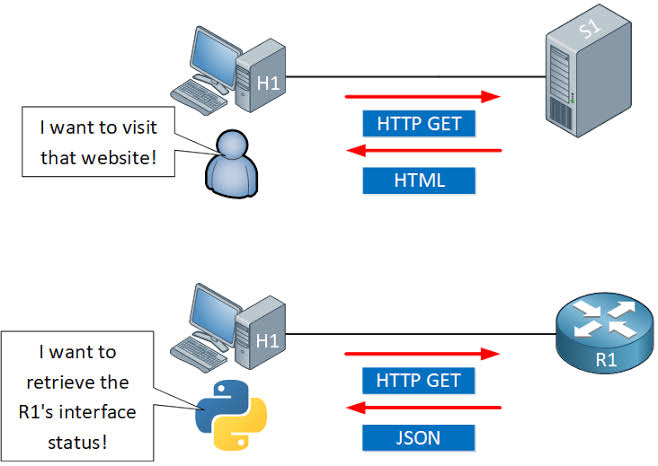
Table of ContentsUnderstanding Cisco REST API Architecture and Automation BasicsCisco REST API vs RESTCONF vs NETCONF: Choosing the Right ProtocolCisco REST API Authentication and Request TemplatesFixing Common Cisco REST API Errors: 401s, Token Expiration, and Timeouts Manually logging into dozens (or thousands) of Cisco devices to push configuration changes doesn't scale — and it's exactly the problem Cisco's REST APIs were built to solve. By exposing device and controller functionality over standard HTTP methods, Cisco REST APIs let engineers automate provisioning, monitoring, and troubleshooting through code instead of CLI sessions. This guide covers how the architecture works, how it stacks up against NETCONF and RESTCONF, hands you working Python and Postman templates, and shows how to resolve the authentication errors that trip up almost everyone the first time they call the API. Understanding Cisco REST API Architecture and Automation Basics Cisco REST APIs follow the same architectural pattern used across the broader software industry: resources (devices, interfaces, policies, sites) are represented as objects, and standard HTTP methods — GET, POST, PUT, DELETE — are used to read or modify them. Most Cisco automation platforms, including DNA Center, Meraki, and ACI, expose their functionality this way rather than requiring engineers to script raw CLI commands. Here's how the architecture fits together in practice: A controller or device exposes an API endpoint. Rather than automating individual routers and switches one by one, most modern Cisco automation happens against a central controller (like Catalyst Center, formerly DNA Center) that manages many devices underneath it. Requests are authenticated before any data is exchanged. Cisco platforms typically use token-based authentication — you authenticate once, receive a session token, and attach that token to subsequent requests instead of resending credentials every time. Data is exchanged as JSON. Both the request bodies (when creating or updating resources) and the response payloads (when reading data) use JSON, which is easy to parse and generate from almost any scripting language. Responses use standard HTTP status codes. A 200 means success, a 401 means an authentication problem, a 404 means the resource doesn't exist, and so on — this predictability is what makes REST APIs so much easier to script against than screen-scraping CLI output. Automation scripts or orchestration tools call the API in place of manual configuration. Common use cases include bulk device onboarding, automated compliance checks, dynamic VLAN provisioning, and pulling real-time telemetry into monitoring dashboards. This model works well for controller-driven, JSON-based automation — but it isn't the only protocol Cisco supports for network management. Understanding where REST fits relative to NETCONF and RESTCONF will help you pick the right tool for your environment. Cisco REST API vs RESTCONF vs NETCONF: Choosing the Right Protocol Cisco devices and controllers support several management protocols, and the differences between them affect how well they fit your automation strategy. Feature Cisco REST API (Platform-specific) RESTCONF NETCONF Data format JSON JSON or XML XML Data modeling standard Vendor/platform-defined YANG-based YANG-based Transport HTTPS HTTPS SSH (typically port 830) Best suited for Controllers (DNA/Catalyst Center, Meraki, ACI) Direct device configuration with structured models Direct device configuration with structured models and transactional changes Configuration validation Platform-dependent Strong, via YANG models Strong, via YANG models Transactional commits (candidate config, rollback) Rarely supported Limited Fully supported Learning curve Low to moderate Moderate (requires YANG familiarity) Higher (requires YANG familiarity and NETCONF operations) In practice, most enterprises end up using more than one of these depending on the layer they're automating. Cisco's platform-specific REST APIs (on DNA Center, Meraki, or ACI) are usually the fastest way to automate at the controller/orchestration level, since they're purpose-built around each platform's own resources. RESTCONF and NETCONF, by contrast, shine when you need standardized, YANG-modeled configuration directly on individual devices — NETCONF in particular is preferred when transactional safety (validate-then-commit, automatic rollback) matters more than ease of use. If your automation strategy centers on a Cisco controller, the platform's own REST API is usually the right starting point — and the templates below will get you making calls quickly. Cisco REST API Authentication and Request Templates Below are ready-to-use templates for authenticating and making calls to Cisco DNA Center / Catalyst Center-style REST APIs. Adjust the base URL and credentials for your platform. python # --- Python: Authenticate and retrieve a token --- import requests from requests.auth import HTTPBasicAuth BASE_URL = "https://[controller-ip]" USERNAME = "[username]" PASSWORD = "[password]" auth_response = requests.post( f"{BASE_URL}/dna/system/api/v1/auth/token", auth=HTTPBasicAuth(USERNAME, PASSWORD), verify=False # Set to True with a valid cert in production ) token = auth_response.json()["Token"] # --- Python: Use the token to call an API endpoint --- headers = { "X-Auth-Token": token, "Content-Type": "application/json" } devices = requests.get( f"{BASE_URL}/dna/intent/api/v1/network-device", headers=headers, verify=False ) print(devices.json()) # --- Postman: Authentication request --- Method: POST URL: https://[controller-ip]/dna/system/api/v1/auth/token Authorization: Basic Auth (username / password) # --- Postman: Authenticated GET request --- Method: GET URL: https://[controller-ip]/dna/intent/api/v1/network-device Headers: X-Auth-Token: {{token}} Content-Type: application/json # --- cURL equivalent --- curl -k -X POST "https://[controller-ip]/dna/system/api/v1/auth/token" \ -u [username]:[password] curl -k -X GET "https://[controller-ip]/dna/intent/api/v1/network-device" \ -H "X-Auth-Token: [token]" These templates cover the core authenticate-then-call pattern used across most Cisco REST APIs. The most common place automation breaks, though, isn't the request logic itself — it's authentication and token handling once scripts run unattended. Fixing Common Cisco REST API Errors: 401s, Token Expiration, and Timeouts Authentication-related failures are by far the most frequent issue engineers run into when automating against Cisco REST APIs. Work through these steps when a script that used to work suddenly starts failing. Confirm the token hasn't expired. Most Cisco controller tokens are short-lived (often around an hour). If a long-running script or scheduled job suddenly starts returning 401 Unauthorized, the token has likely expired mid-run — build in logic to re-authenticate and refresh the token before it lapses, rather than authenticating once at the start of a long process. Check that the token is being sent in the correct header. A surprisingly common cause of persistent 401 errors is simply sending the token in the wrong header name or format — double-check the platform's documentation for the exact header expected (e.g., X-Auth-Token versus an Authorization: Bearer header, which varies by Cisco platform). Verify the account has the right role and permissions. A valid token can still produce 401 or 403 errors if the authenticated user lacks permission for that specific API endpoint — check the user's role assignment on the controller. Resolve SSL certificate validation failures. If requests fail with certificate errors rather than clean HTTP status codes, it's usually because the controller is using a self-signed certificate. For production scripts, install the proper certificate chain rather than permanently disabling verification, which should only be used temporarily in lab environments. Diagnose connection timeouts separately from authentication errors. A timeout with no HTTP response at all usually points to a network reachability issue, a firewall blocking the API port, or the controller being overloaded — check basic connectivity to the controller's management interface before assuming it's an API-level problem. Add retry logic with backoff for transient failures. Controllers under heavy load may intermittently reject valid requests; a short retry with exponential backoff resolves most of these without masking genuine, persistent errors. Working through token validity, header formatting, permissions, and connectivity in that order resolves the overwhelming majority of Cisco REST API errors without needing to dig through controller logs. -
- 433
- SPOTO
- 2026-07-31 15:24
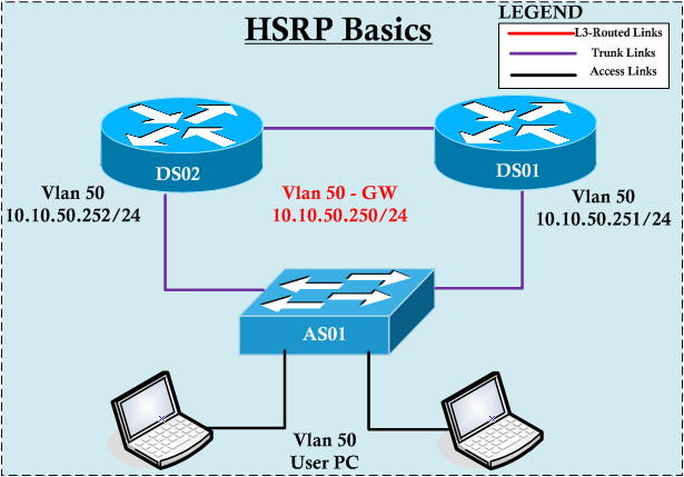
Table of ContentsHow HSRP Works and How to Configure It Step by StepHSRP Version 1 vs Version 2: Which Should You Deploy?Ready-to-Use HSRP Configuration TemplatesTroubleshooting Common HSRP Issues Network downtime caused by a single point of failure at the default gateway is one of the most preventable outages in enterprise networking. Cisco's Hot Standby Router Protocol (HSRP) solves this by letting two or more routers share a virtual IP address, so if the active router fails, a standby router takes over automatically — often without end users ever noticing. This guide walks through the fundamentals of HSRP, compares its two protocol versions, hands you ready-to-use configuration templates, and shows how to troubleshoot the issues that trip up even experienced engineers. How HSRP Works and How to Configure It Step by Step HSRP creates a "virtual router" made up of a virtual IP address and a virtual MAC address, shared across a group of physical routers on the same subnet. One router is elected active (it forwards traffic sent to the virtual IP), another is elected standby (it takes over if the active fails), and any others sit in a listen state ready to participate in the next election. End hosts only need to know the virtual IP as their default gateway — they never need to be reconfigured, even after a failover. Here's how to set it up on two Cisco IOS routers: Enable routing and configure the physical interfaces. Each router needs its own unique IP address on the shared subnet before HSRP can be layered on top. Choose an HSRP group number. Group numbers identify which routers belong to the same virtual router instance — this matters when you run multiple HSRP groups on the same interface (e.g., for load balancing across VLANs). Assign the virtual IP address with the standby <group> ip <virtual-ip> command on the relevant interface of every participating router. Set priorities to control which router becomes active. The router with the higher priority (default is 100) wins the election. Assign your primary router a higher value, like 110. Enable preemption if you want the higher-priority router to reclaim the active role automatically once it comes back online after a failure — without this, a recovered router stays in standby until the next election trigger. Verify the group state with show standby brief to confirm one router shows Active and the other shows Standby for the group. Once these steps are complete, point your hosts' default gateway at the virtual IP, and the pair is ready to survive a router failure transparently. The next question most teams face is which version of HSRP to actually deploy — that depends on a few feature differences worth knowing before you commit. HSRP Version 1 vs Version 2: Which Should You Deploy? Cisco IOS defaults to HSRP version 1, but version 2 is generally the better choice for modern networks. The table below breaks down the practical differences that matter when deciding. Feature HSRP v1 HSRP v2 Group number range 0–255 0–4095 Multicast address used 224.0.0.2 224.0.0.102 IPv6 support No Yes Virtual MAC address format 0000.0C07.ACxx (xx = group in hex) 0000.0C9F.Fxxx Millisecond timers Not supported Supported Authentication Plain text only Plain text and MD5 Interoperability Can't interoperate with v2 devices in the same group Can't interoperate with v1 devices in the same group For most new deployments, v2 is the practical default: it supports far more HSRP groups per interface, allows sub-second failover with millisecond timers, and adds MD5 authentication for better security. The main reason to stay on v1 is compatibility with older Cisco hardware or existing configurations that haven't been migrated. To explicitly select a version, use standby version 2 (or 1) under the interface before configuring the group — mixing versions in the same group on different routers will prevent them from forming a proper HSRP pair. With the version decision made, here are the actual commands to get a group running. Ready-to-Use HSRP Configuration Templates Below are standard Cisco IOS CLI snippets you can adapt directly. Replace the bracketed placeholders with your own values. ! --- Basic HSRP group configuration --- interface [interface-id] ip address [ip-address] [subnet-mask] standby version 2 standby [group-number] ip [virtual-ip-address] standby [group-number] priority [value] standby [group-number] preempt ! --- Example: Router A (intended primary) --- interface GigabitEthernet0/1 ip address 10.10.10.2 255.255.255.0 standby version 2 standby 1 ip 10.10.10.1 standby 1 priority 110 standby 1 preempt ! --- Example: Router B (intended backup) --- interface GigabitEthernet0/1 ip address 10.10.10.3 255.255.255.0 standby version 2 standby 1 ip 10.10.10.1 standby 1 priority 100 standby 1 preempt ! --- Add MD5 authentication (v2 only) --- interface GigabitEthernet0/1 standby 1 authentication md5 key-string [shared-secret] ! --- Adjust hello and hold timers (v2 supports msec) --- interface GigabitEthernet0/1 standby 1 timers msec 200 msec 750 ! --- Enable interface tracking so priority drops on uplink failure --- interface GigabitEthernet0/1 standby 1 track [interface-id] decrement [value] ! --- Verification commands --- show standby brief show standby [interface-id] [group-number] These snippets cover the majority of deployment scenarios, but HSRP has a handful of failure modes that only show up once a group is live and handling real traffic — that's where troubleshooting skills come in. Troubleshooting Common HSRP Issues Even a correctly typed configuration can misbehave once it's exposed to real network conditions. Here's how to work through the most common problems. Diagnose split-brain (dual-active) scenarios first. If both routers claim to be active simultaneously, it usually means HSRP hello packets aren't reaching one another — check for an access list blocking multicast traffic, a mismatched HSRP version between routers, or a physical link failure on the segment carrying hellos. show standby on both routers will confirm if each believes it's active. Check for state flapping between Active and Standby. Flapping is commonly caused by timers set too aggressively for the link's actual latency, or by intermittent packet loss on the shared segment. Loosening the hello/hold timers slightly, or investigating the underlying link quality, usually resolves it. Review preempt delay if failover happens before the router is truly ready. A recovering router may win the election via preemption before its routing table or upstream links have fully converged, causing brief blackholing. Use standby [group] preempt delay minimum [seconds] to force a wait period before the router reclaims active status. Confirm object tracking is actually decrementing priority. If a router with a failed uplink still refuses to relinquish the active role, verify the tracked object (interface or IP SLA) is correctly referenced and that the priority decrement is large enough to drop below the peer's priority — a decrement of 1 rarely changes the election outcome. Validate authentication consistency. If routers stop seeing each other's hellos and everything else looks correct, mismatched or expired MD5 keys are a common silent cause, especially after a password rotation. Watch for version or group-number mismatches. Two routers running different HSRP versions, or with a typo in the group number, will never form a pair — they'll just sit as two independent "active" routers indefinitely, which looks identical to split-brain at first glance. Working through these checks in order — from packet reachability, to timers, to tracking logic — resolves the vast majority of real-world HSRP issues without needing to tear down and rebuild the configuration from scratch. -
- 486
- SPOTO
- 2026-07-31 15:16
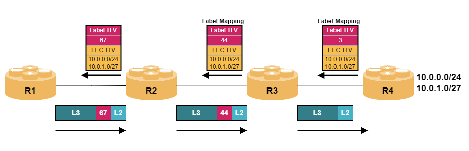
Table of ContentsTroubleshooting an LDP Neighbor Down: The Systematic WorkflowTargeted LDP vs. Link-Local LDP: Key Structural DifferencesTransport Address Mismatches and TCP Port 646 FailuresLDP Neighbor Troubleshooting Command Cheat Sheet: Cisco and Juniper An LDP neighbor showing "down" is one of those MPLS problems that can stem from several completely different layers — IGP reachability, a UDP discovery mismatch, a blocked TCP session, or a targeted-versus-link-local configuration mismatch. Because the symptom looks identical regardless of cause, working through the right layers in the right order is what separates a five-minute fix from an hour of guessing. This guide walks through a systematic troubleshooting workflow, compares the two LDP discovery mechanisms, digs into the transport-layer issues that trip people up most, and closes with a full verification command reference across Cisco and Juniper. Troubleshooting an LDP Neighbor Down: The Systematic Workflow LDP session establishment happens in two distinct phases — UDP-based discovery, then a TCP-based session — and knowing which phase is failing narrows the cause dramatically. Confirm IGP reachability between the two routers first. LDP relies entirely on the underlying IGP (OSPF, IS-IS, etc.) for reachability to the neighbor's transport address — if the IGP itself doesn't have a route to that address, LDP has no chance of establishing a session regardless of anything else being correctly configured. router# show ip route <neighbor-transport-address> Check whether LDP discovery (Hello) is happening at all. LDP Hello packets are sent via UDP to port 646, either as link-local multicast (for directly connected neighbors) or as targeted unicast (for non-directly-connected neighbors) — confirm Hellos are being seen before assuming the problem is deeper in the TCP session. router# show mpls ldp discovery Check the current LDP neighbor/session state. This tells you not just whether the session is up or down, but often the specific reason, if the platform surfaces one. router# show mpls ldp neighbor Determine whether the failure is at discovery (UDP) or session (TCP) stage. If discovery shows the neighbor but the session never establishes, the problem is almost certainly TCP port 646 connectivity or a transport address mismatch — covered in depth in the next section. If discovery itself shows nothing, the problem is more likely IGP reachability, interface-level LDP enablement, or a mismatched Hello interval/hold time. Confirm LDP is actually enabled on the correct interface. A surprisingly common cause of "no discovery at all" is simply forgetting to enable LDP on the interface facing the neighbor, especially after an interface was reconfigured or replaced. router# show mpls interfaces Check for a label distribution protocol mismatch. Confirm both routers are actually running LDP (rather than one running the legacy Tag Distribution Protocol, or a mismatched RSVP-TE-only configuration) — an obvious check, but one worth confirming explicitly rather than assuming. router# show mpls ldp parameters Check for MTU-related session instability. Similar to other control-plane protocols, an MTU mismatch across the link can cause LDP sessions to flap rather than simply fail to establish — if the session comes up briefly and drops repeatedly rather than never forming at all, suspect this before deeper configuration issues. router# show interfaces <interface> | include MTU Re-verify after each change, one variable at a time. As with most control-plane troubleshooting, changing multiple things simultaneously makes it much harder to know what actually fixed the problem — confirm neighbor state after each individual adjustment. router# show mpls ldp neighbor detail This layered approach — IGP reachability, then discovery, then session establishment — mirrors how LDP itself builds a relationship, which is exactly why working through it in this order consistently narrows down the cause fastest. Targeted LDP vs. Link-Local LDP: Key Structural Differences Not every LDP neighbor relationship is discovered the same way, and knowing which type you're dealing with changes what you should check first. Criteria Link-Local (Basic) LDP Targeted LDP Discovery mechanism UDP multicast Hello sent directly on a shared link UDP unicast Hello sent to a specific, often non-directly-connected, address Typical use case Directly connected MPLS-enabled links between adjacent routers Non-directly-connected neighbors, such as across a Layer 2 access network, for pseudowire/VPLS setups, or session backup/redundancy scenarios Configuration requirement Usually automatic once LDP is enabled on the interface Requires explicit configuration specifying the target neighbor's address Dependency on IGP Relies on IGP only for the transport address resolution used during TCP session setup, not for Hello delivery itself (which is link-local) Relies fully on IGP reachability for both Hello delivery (since it's unicast, routed) and transport address resolution Common failure mode Interface-level misconfiguration (LDP not enabled), or a directly connected Layer 1/2 issue Missing or incorrect target address configuration, or a routing path failure between the two non-adjacent routers Diagnostic starting point Confirm LDP is enabled on the correct interface first Confirm the targeted neighbor statement is present and the address is reachable via the IGP first Common Cisco config command mpls ip on the interface mpls ldp neighbor <address> targeted The practical distinction that matters most for troubleshooting: a link-local LDP failure is almost always a Layer 1/2 or interface-configuration problem local to that link, while a targeted LDP failure is almost always a routing (IGP) or explicit-configuration problem — start your investigation in the layer that matches which type of session you're actually dealing with. Transport Address Mismatches and TCP Port 646 Failures When LDP discovery succeeds but the session never actually establishes, the problem has moved from the UDP discovery phase into the TCP session phase — and this is where transport address and connectivity issues live. Understand what the LDP transport address actually is. After discovery, LDP routers use a specific IP address — typically a loopback interface by default — to establish the actual TCP session on port 646. This transport address is advertised within the Hello packet itself. Recognize the classic transport address mismatch scenario. If one router's advertised transport address isn't reachable from the other router (for example, its loopback isn't being advertised into the IGP, or is filtered), discovery can succeed via a directly connected interface while the TCP session fails, since the session attempt targets an address that can't actually be reached. Verify the transport address being advertised. router# show mpls ldp discovery detail Confirm the advertised transport address is reachable via the IGP. This is the single most common root cause of "discovery works, session doesn't" — check specifically for the transport address, not just the interface's directly connected address. router# show ip route <advertised-transport-address> Check for an access list or firewall blocking TCP port 646. Unlike the UDP Hello packets, the LDP session itself is TCP-based, so a stateful firewall or ACL that permits UDP 646 but blocks TCP 646 (or vice versa) will produce exactly this "discovery succeeds, session fails" pattern. router# show access-lists router# show ip access-lists interface <interface> Confirm the TCP session state directly if available on your platform. Some platforms expose LDP's underlying TCP connection state directly, which can confirm whether the router is even attempting the TCP handshake. router# show tcp brief | include 646 Fix a transport address mismatch by aligning IGP advertisement. If the issue is that a loopback used as the transport address isn't in the IGP, the fix is typically to ensure that loopback is included in the IGP's network statements or redistribution, or to explicitly configure LDP to use a different, already-reachable interface as its transport address. router(config)# mpls ldp router-id <interface> force Fix a blocking ACL by explicitly permitting TCP port 646 between the two routers. Make sure any ACL applied to the relevant interface allows both the UDP discovery traffic and the TCP session traffic — a common mistake is fixing one and forgetting the other. router(config)# ip access-list extended LDP-PERMIT router(config-ext-nacl)# permit tcp host <router-a-ip> host <router-b-ip> eq 646 router(config-ext-nacl)# permit udp host <router-a-ip> host <router-b-ip> eq 646 Re-verify the full session state after resolving transport or ACL issues. Confirm the session moves from a discovery-only state to a fully established neighbor relationship, not just that traffic is no longer being blocked. router# show mpls ldp neighbor detail Once the transport address is confirmed reachable via the IGP and any ACLs or firewalls explicitly permit both UDP and TCP traffic on port 646, LDP sessions that were stuck at the discovery stage almost always complete and move to established state without further intervention. LDP Neighbor Troubleshooting Command Cheat Sheet: Cisco and Juniper For quick reference during troubleshooting, here's a consolidated command set covering discovery, session state, transport address, and platform-specific syntax across both major vendors. # --- Cisco IOS/IOS-XE: Discovery and neighbor state --- router# show mpls ldp discovery # Hello-based discovery status router# show mpls ldp discovery detail # Includes advertised transport address router# show mpls ldp neighbor # Current neighbor/session state router# show mpls ldp neighbor detail # Full session detail including timers # --- Cisco IOS/IOS-XE: Interface and parameters --- router# show mpls interfaces # Confirm LDP enabled per interface router# show mpls ldp parameters # Global LDP configuration/session parameters router(config-if)# mpls ip # Enable LDP on an interface (link-local) router(config)# mpls ldp neighbor <address> targeted # Configure targeted LDP session router(config)# mpls ldp router-id <interface> force # Set explicit transport/router ID # --- Cisco IOS/IOS-XE: Transport and connectivity checks --- router# show ip route <transport-address> # Confirm IGP reachability router# show access-lists # Check for blocking ACLs router# show tcp brief | include 646 # Check TCP session state directly # --- Juniper Junos: Discovery and neighbor state --- > show ldp neighbor # Current neighbor/discovery state > show ldp session # TCP session state and detail > show ldp session detail # Full session parameters > show ldp interface # Confirm LDP enabled per interface > show ldp database # Label bindings learned # --- Juniper Junos: Configuration --- # set protocols ldp interface <interface-name> # Enable LDP on an interface # set protocols ldp session <neighbor-address> # Configure targeted session # set protocols mpls interface <interface-name> # Enable MPLS on an interface # --- Cross-platform packet capture (last resort) --- router# debug mpls ldp transport events # Cisco: TCP transport events router# debug mpls ldp messages # Cisco: Hello/session message exchange Keep the "discovery detail" and transport-address reachability checks near the top of your workflow — in both Cisco and Juniper environments, that combination diagnoses the large majority of LDP neighbor-down cases faster than reaching for debug output. -
- 747
- SPOTO
- 2026-07-31 15:09
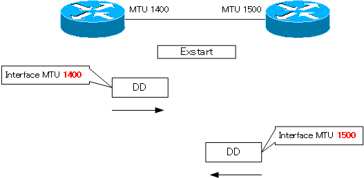
Table of ContentsWhy OSPF Gets Stuck in EXSTART or EXCHANGEEXSTART vs. INIT vs. LOADING: Comparing OSPF Stuck StatesFixing an OSPF Neighbor Stuck in EXSTART: Step by StepOSPF EXSTART Troubleshooting Command Cheat Sheet An OSPF neighbor stuck in EXSTART is one of the most common — and most misunderstood — adjacency failures in production networks and lab scenarios alike. The link is up, you can ping the neighbor, but the adjacency refuses to progress past EXSTART or EXCHANGE, and routes never populate. This guide walks through exactly why that happens, how EXSTART differs from other stalled states, the precise steps to fix it, and a diagnostic command reference to speed up the next time it happens. Why OSPF Gets Stuck in EXSTART or EXCHANGE Before fixing anything, it helps to understand what EXSTART and EXCHANGE are actually trying to accomplish, since that's what reveals why they stall. Understand what EXSTART is for. In this state, two OSPF routers negotiate master/slave roles and the initial Database Description (DBD) sequence number, before actually exchanging any topology information — think of it as a handshake that has to succeed before real data exchange begins. Understand what EXCHANGE is for. Once master/slave roles are settled, routers move into EXCHANGE and start actually sending DBD packets describing their link-state databases — this is where the real content of the negotiation happens, and where a stall often first becomes visible even though the root cause originated in EXSTART. Recognize MTU mismatch as the most common root cause. If two routers have different Maximum Transmission Unit settings on the connecting interface, DBD packets sized for the larger MTU can be dropped or silently truncated by the router with the smaller MTU, since OSPF (unlike some protocols) doesn't automatically fragment these control packets — the neighbor relationship stalls repeatedly at the same point rather than failing outright. Recognize duplicate router IDs as another major cause. If two routers in the same OSPF domain end up with identical router IDs (often because both were left to auto-select based on loopback or interface IPs, and those happened to collide, or were cloned from a template), the adjacency can flap or stall unpredictably, since OSPF relies on router ID uniqueness for proper LSA origination and acknowledgment tracking. Recognize unicast/unreachable adjacency issues. Since EXSTART and EXCHANGE packets are sent via unicast (unlike the multicast Hello packets used for initial discovery), an access list, firewall, or asymmetric routing issue that blocks unicast traffic between the two routers — while still permitting multicast Hellos — can allow the neighbor to reach 2-WAY or INIT but never progress further. Recognize interface queue or CPU-related drops as a less common but real cause. On heavily loaded routers or links experiencing packet loss, DBD packets can be dropped in transit even without a configuration mismatch, causing the same symptom through a purely environmental cause rather than a settings problem. Understand why the symptom looks identical across these different causes. All of the above manifest the same way — an adjacency cycling between EXSTART and EXCHANGE, or stalling entirely — which is exactly why a systematic diagnostic approach (covered later in this guide) matters more than guessing based on the symptom alone. Knowing these root causes in advance makes it much easier to interpret exactly where in the neighbor state machine a given adjacency is actually failing — which is the next useful distinction to make before diving into remediation. EXSTART vs. INIT vs. LOADING: Comparing OSPF Stuck States Not every stalled OSPF adjacency is an EXSTART problem — different stuck states point to different root causes and require different fixes. Criteria Stuck in INIT Stuck in EXSTART/EXCHANGE Stuck in LOADING What's already succeeded Nothing yet — router has only received a Hello without seeing itself listed in return Basic Hello-based two-way communication has succeeded, and master/slave negotiation may have started DBD exchange has completed successfully; routers have agreed on what LSAs each needs What's failing The neighbor either isn't receiving this router's Hello, or the neighbor list in received Hellos doesn't include this router Master/slave negotiation stalls, or DBD packets aren't being reliably exchanged Link-State Request/Update packets for specific LSAs aren't being received or acknowledged Most common root cause One-way communication — often an access list, mismatched Hello/Dead timers, or a physical layer issue affecting only one direction MTU mismatch (most common) or duplicate router ID (second most common) Packet loss or unicast reachability issues affecting the larger LSU/LSAck exchange rather than DBD packets specifically Typical fix Check ACLs, confirm timer values match, verify Layer 1/2 stability in both directions Fix MTU mismatch or resolve router ID collision Check for the same unicast reachability or packet-loss issues that affect EXSTART, since LOADING relies on the same underlying transport Diagnostic priority Verify Hello packets are being seen bidirectionally first Check MTU on both sides first, then router ID uniqueness Check for packet loss/drops on the link, then unicast reachability The practical value of this comparison: knowing which state an adjacency is actually stuck in immediately narrows your list of likely causes — a router stuck in INIT almost never has an MTU problem, and a router stuck in EXSTART almost never has a simple ACL-blocking-Hello issue, since it already got past that stage. Fixing an OSPF Neighbor Stuck in EXSTART: Step by Step With root causes and state context established, here's the systematic sequence to actually diagnose and resolve the stall. Confirm the neighbor is genuinely stuck, not just slow. Check the neighbor state a few times over a short interval — a router that's actually stuck will show the same state (or cycle between EXSTART and EXCHANGE) repeatedly rather than progressing to FULL. router# show ip ospf neighbor Check interface MTU on both routers first — this resolves the majority of cases. Compare the MTU values directly; even a small mismatch (such as one router at 1500 and the other at 1492 due to a tunnel or encapsulation difference) is enough to cause the stall. router# show interfaces <interface> | include MTU Fix a genuine MTU mismatch by aligning the values. Whenever possible, correct the actual MTU setting on the interface with the lower value, rather than working around it, since a real mismatch may cause other issues beyond OSPF. router(config-if)# mtu 1500 If aligning MTU isn't practical, use ip ospf mtu-ignore as a targeted workaround. This tells OSPF to skip MTU verification during DBD exchange entirely — useful when the MTU difference is intentional (such as certain tunnel interfaces) rather than a misconfiguration, but apply it deliberately, not as a default troubleshooting reflex. router(config-if)# ip ospf mtu-ignore Check for duplicate router IDs if MTU checks out clean. Compare router IDs across the OSPF domain, not just between the two neighbors directly involved — a duplicate elsewhere in the topology can still cause instability. router# show ip ospf | include Router ID Resolve a duplicate router ID by setting it explicitly. Rather than relying on automatic selection from an interface or loopback address, set the router ID directly and predictably. router(config-router)# router-id 10.255.255.1 Clear the OSPF process after a router ID change. A router ID change doesn't take effect on an already-established process without a reset. router# clear ip ospf process Check for unicast reachability issues if MTU and router ID both check out. Confirm there's no access list, firewall, or asymmetric routing path blocking unicast traffic between the two routers specifically — remember that multicast Hellos succeeding doesn't guarantee unicast DBD/LSU traffic will. router# ping <neighbor-ip> source <local-interface> Re-verify neighbor state after each change. Don't stack multiple fixes before checking — verify after each individual change so you know definitively which one resolved the issue, which matters both for real troubleshooting and for lab scenarios where you may need to explain your reasoning. router# show ip ospf neighbor detail Working through MTU, then router ID, then unicast reachability, in that order, resolves the overwhelming majority of real-world EXSTART stalls — and doing it in this specific order matters, since MTU and router ID issues are both far more common and far faster to check than deeper reachability problems. OSPF EXSTART Troubleshooting Command Cheat Sheet For quick reference the next time an adjacency stalls, here's a consolidated diagnostic command set covering verification, debugging, and the fixes covered above. # --- Quick state check --- router# show ip ospf neighbor # Current state of all neighbors router# show ip ospf neighbor detail # Detailed per-neighbor state and timers # --- MTU diagnosis and fix --- router# show interfaces <interface> | include MTU # Compare MTU on both routers router(config-if)# mtu 1500 # Align MTU to matching value router(config-if)# ip ospf mtu-ignore # Bypass MTU check (use deliberately) # --- Router ID diagnosis and fix --- router# show ip ospf | include Router ID # Check router ID domain-wide router(config-router)# router-id <unique-id> # Set explicit router ID router# clear ip ospf process # Required after router-id change # --- Unicast reachability check --- router# ping <neighbor-ip> source <local-interface> # Confirm unicast path works router# show ip route <neighbor-ip> # Confirm routing path to neighbor router# show access-lists # Check for blocking ACLs # --- Deep diagnostics (verbose output, use narrowly) --- router# debug ip ospf adj # Adjacency formation events router# debug ip ospf packet # Raw OSPF packet exchange router# debug ip ospf events # General OSPF process events router# undebug all # Stop all debugging # --- Interface-level OSPF detail --- router# show ip ospf interface <interface> # Timers, area, network type, cost Keep the MTU and router ID checks at the top of your muscle memory — in both production troubleshooting and timed lab scenarios, those two commands resolve the stall far more often than anything requiring debug output. -
- 413
- SPOTO
- 2026-07-31 14:58
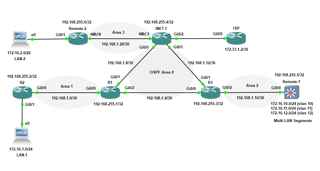
Table of ContentsAdvanced Multi-Area OSPF Design: Stub Areas, NSSA, and Path SelectionComparing OSPF Network Types: Timers, DR/BDR, and Neighbor BehaviorTroubleshooting OSPF Adjacency, LSA Filtering, and Virtual Link FailuresCCIE Lab OSPF Practice Workbook: Topology and Configuration Templates OSPF is one of the most heavily tested protocols in the CCIE Enterprise Infrastructure lab, precisely because its flexibility creates so many places for a misconfiguration to hide — area types that behave differently, network types with wildly different neighbor and timer behavior, and LSA filtering rules that determine what routes actually make it across an area boundary. This guide works through advanced multi-area design, how the different OSPF network types compare, a systematic troubleshooting approach for the failures that show up most often in lab scenarios, and closes with a practice workbook to drill all of it under time pressure. Advanced Multi-Area OSPF Design: Stub Areas, NSSA, and Path Selection Beyond a flat, single-area OSPF design, the lab expects fluency with special area types and the controls that shape path selection across them. Understand why special area types exist. Backbone-adjacent areas often don't need full visibility into external (Type 5) routes redistributed from other protocols — stub area types exist specifically to reduce the size of the routing table and LSA database on routers that don't need that information. Configure a stub area to block external routes. A stub area prevents Type 5 (external) LSAs from entering, replacing them with a single default route injected by the ABR — every router in the area must be configured as stub for the area to form correctly. router(config-router)# area 10 stub Configure a totally stubby area for maximum summarization (Cisco-specific). This further blocks Type 3 (inter-area) LSAs in addition to Type 5, leaving only a default route — this option is Cisco-proprietary and only needs to be configured on the ABR. router(config-router)# area 10 stub no-summary Configure an NSSA when the area itself needs to redistribute external routes. A Not-So-Stubby Area behaves like a stub area but allows limited external route injection via Type 7 LSAs, which get translated to Type 5 by the ABR when leaving the area — this is the scenario tested when a lab topology has a redistribution point sitting inside what would otherwise be a stub area. router(config-router)# area 20 nssa Control Type 7-to-Type 5 translation behavior explicitly when required. By default, the NSSA ABR with the highest router ID performs translation — lab scenarios sometimes require forcing this role onto a specific router. router(config-router)# area 20 nssa translate type7 always Use route summarization at area boundaries to control LSA propagation. Summarizing routes at the ABR reduces the number of Type 3 LSAs flooded into other areas — a common lab requirement when a task specifies "advertise only a summary route for area X." router(config-router)# area 10 range 10.1.0.0 255.255.0.0 Control path selection with cost manipulation rather than relying on defaults. OSPF path selection tasks in the lab frequently require influencing which of several equal- or near-equal-cost paths is preferred — interface cost is the most direct and commonly tested lever. router(config-if)# ip ospf cost 20 Use virtual links only when the topology genuinely requires them. A virtual link is a workaround for an area that isn't physically connected to the backbone (Area 0) — lab scenarios test this specifically when an area's ABR can't directly reach Area 0, requiring a logical tunnel through a transit area instead. router(config-router)# area 1 virtual-link 10.1.1.1 With area types and path-selection controls in place, the next layer of complexity is choosing (or correctly interpreting) the OSPF network type running on each link, since that single setting changes neighbor behavior, timers, and DR/BDR requirements substantially. Comparing OSPF Network Types: Timers, DR/BDR, and Neighbor Behavior OSPF's default network type depends on the underlying interface type, but the lab frequently requires overriding it — understanding exactly what changes between types is essential to avoid a neighbor relationship that silently behaves differently than intended. Criteria Broadcast Point-to-Point Non-Broadcast (NBMA) Point-to-Multipoint Default on Ethernet interfaces Serial (HDLC/PPP) interfaces Frame Relay/ATM interfaces (main interface, multipoint) Not a default — must be manually configured DR/BDR election Yes — required No — not needed, both routers are equal peers Yes — required No — not needed Hello timer (default) 10 seconds 10 seconds 30 seconds 30 seconds Dead timer (default) 40 seconds 40 seconds 120 seconds 120 seconds Neighbor discovery Automatic via multicast Hello Automatic via multicast Hello Manual — requires neighbor statements Automatic via multicast Hello Route advertisement type Network (subnet-wide) Network (subnet-wide) Network (subnet-wide) Host routes (/32) for each neighbor Common lab pitfall Forgetting DR/BDR election depends on priority, and a priority-0 router will never become DR Assuming DR/BDR election happens when it doesn't apply to this type at all Forgetting manual neighbor statements, causing adjacencies to silently never form Mismatched timers between manually configured point-to-multipoint interfaces Typical lab trigger Standard LAN segment scenarios Serial or GRE tunnel point-to-point links Legacy Frame Relay hub-and-spoke topologies Frame Relay or DMVPN hub-and-spoke needing simpler neighbor management than NBMA The critical lab skill here isn't memorizing defaults — it's recognizing when a scenario requires you to override the default network type explicitly (a very common ask, especially on Frame Relay or GRE tunnel interfaces), and remembering that Hello/Dead timers must match between neighbors for an adjacency to form at all, regardless of which network type is in use. Troubleshooting OSPF Adjacency, LSA Filtering, and Virtual Link Failures When OSPF doesn't behave as expected in a lab scenario, work through this sequence rather than guessing. Confirm basic reachability and interface state first. As with any routing protocol, OSPF can't form neighbors over a broken or misconfigured physical/IP layer — verify this before looking at OSPF-specific configuration. router# show ip interface brief Check neighbor state if an adjacency won't fully form. A neighbor stuck in a state other than FULL (such as 2-WAY on a broadcast/NBMA network where DR/BDR election matters, or EXSTART/EXCHANGE) points to specific, well-known causes. router# show ip ospf neighbor Diagnose a neighbor stuck in EXSTART/EXCHANGE. This is almost always an MTU mismatch — OSPF routers exchanging Database Description packets with mismatched MTU will fail to progress past this state, since large LSAs can't be reliably exchanged. router# show interfaces <interface> | include MTU Diagnose a neighbor that never appears at all. Check for a mismatch in area ID, Hello/Dead timers, authentication, or subnet mask between the two routers — any of these will prevent the neighbor relationship from forming in the first place, similar in spirit to the hard-match requirements found in other IGPs. router# show ip ospf interface <interface> Diagnose routes missing from an area that should be receiving them. This is where stub/NSSA area type and summarization configuration (covered above) become the primary suspects — confirm both ends of an area boundary agree on the area type, since a mismatch here will actually prevent the adjacency from forming at all rather than just filtering routes silently. router# show ip ospf database Diagnose external routes missing on the far side of an NSSA. If Type 7 LSAs aren't being translated to Type 5 as expected, confirm which ABR is performing translation — remember only one ABR per NSSA translates by default, based on highest router ID, unless explicitly overridden. router# show ip ospf database nssa-external Diagnose a virtual link that won't come up. Confirm the transit area used for the virtual link is not itself a stub area (virtual links cannot transit stub areas), and confirm the router IDs referenced in the virtual-link command are correct on both ends. router# show ip ospf virtual-links Diagnose an unexpected routing loop or suboptimal path. Check for inconsistent cost configuration across parallel paths, and confirm route summarization at ABRs isn't unintentionally hiding more specific routes that would have been preferred. router# show ip route ospf router# show ip ospf border-routers Confirm LSA type visibility matches the area design intent. Use the database summary to quickly confirm whether Type 3, 5, or 7 LSAs are present where expected (or absent where they should be filtered), rather than inferring this purely from the routing table. router# show ip ospf database database-summary Working through interface/reachability, neighbor state, area type and timer agreement, and finally LSA visibility in that order will resolve the large majority of OSPF issues that show up in lab scenarios — and it mirrors exactly how OSPF itself builds an adjacency, from the bottom up. CCIE Lab OSPF Practice Workbook: Topology and Configuration Templates Use the templates below to build timed practice scenarios covering multi-area design, network types, and the troubleshooting sequence above. CCIE LAB OSPF PRACTICE TOPOLOGY TEMPLATE =========================================== Suggested minimum topology: R1 (Area 0, ABR) --- R2 (Area 0, ABR) --- R3 (Area 20, NSSA) R1 --- R4 (Area 10, totally stubby, broadcast network type) R2 --- R5 (Area 1, no direct Area 0 connectivity - virtual link) R3 --- R6 (external redistribution point inside NSSA) Practice scenario checklist: [ ] Configure Area 10 as totally stubby, verify only a default route reaches R4 [ ] Configure Area 20 as NSSA, redistribute a static route on R6, verify Type 7 -> Type 5 translation at R3 [ ] Force NSSA translation onto a specific router using "area X nssa translate type7 always" [ ] Configure a virtual link from R5 through Area 1 to reach Area 0, verify adjacency comes up [ ] Set the R1-R4 link to a manually configured network type different from its default, verify DR/BDR behavior changes accordingly [ ] Intentionally mismatch MTU on one link, observe neighbor stuck in EXSTART, then fix using only verification commands [ ] Summarize routes at an ABR using "area X range", confirm fewer, aggregated Type 3 LSAs appear in the adjacent area QUICK CONFIG TEMPLATE — FILL IN THE BLANKS ============================================= # Basic process and area assignment router ospf ____________ router-id ____________ network ____________ ____________ area ____________ # Stub / totally stubby / NSSA area ____________ stub # stub area ____________ stub no-summary # totally stubby (ABR only) area ____________ nssa # NSSA area ____________ nssa translate type7 always # force translation # Summarization at ABR area ____________ range ____________ ____________ # Virtual link area ____________ virtual-link ____________ # Network type override interface ____________ ip ospf network ____________ # broadcast / point-to-point / # non-broadcast / point-to-multipoint # NBMA manual neighbor (if network type requires it) router ospf ____________ neighbor ____________ # Path selection interface ____________ ip ospf cost ____________ Time yourself building this topology end to end, then deliberately break one variable at a time — an MTU mismatch, a wrong area type, a missing NBMA neighbor statement — and practice diagnosing it using only the verification commands from the troubleshooting section above, without removing or rebuilding configuration. That's precisely the muscle memory the lab format rewards. -
- 562
- SPOTO
- 2026-07-31 14:51
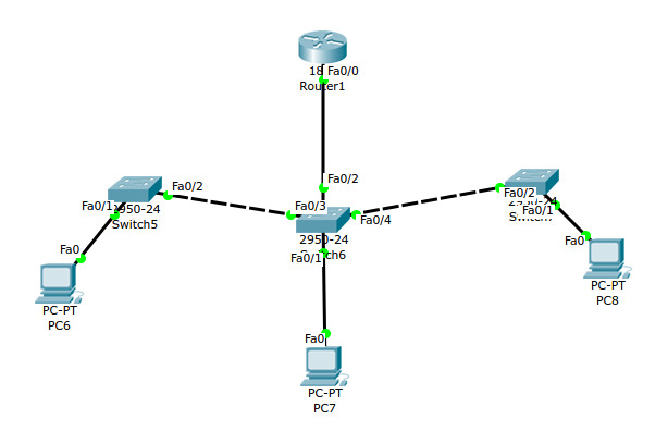
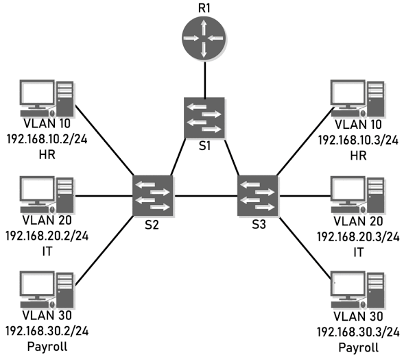
Table of ContentsHow Cisco Trunking Actually Works: 802.1Q, Tagging, and the Native VLAN802.1Q vs. ISL, and DTP Negotiation Modes ComparedTroubleshooting Trunk Failures: Native VLAN Mismatches, Pruning, and DTPCisco Trunk Configuration and Troubleshooting Command Cheat Sheet A trunk link is what lets a single physical connection between two switches carry traffic for dozens of VLANs simultaneously — but that convenience depends on both ends agreeing on encapsulation, native VLAN, and negotiation mode. Get any of those out of sync and you end up with a link that looks "up" but silently drops or misroutes traffic. This guide covers how trunking actually works at the frame level, how 802.1Q compares to its now-legacy predecessor, the exact diagnostic steps for the most common trunk failures, and a full command reference to keep on hand. How Cisco Trunking Actually Works: 802.1Q, Tagging, and the Native VLAN Before troubleshooting a trunk, it helps to understand exactly what's happening to a frame as it crosses one. Understand the problem trunking solves. A single access port can only belong to one VLAN, which would mean a dedicated physical link between switches for every VLAN in the network — trunking eliminates that by letting one link carry traffic for many VLANs at once. Learn how 802.1Q identifies which VLAN a frame belongs to. As a frame crosses a trunk link, the switch inserts a 4-byte 802.1Q tag into the Ethernet header, containing a 12-bit VLAN ID field that identifies which of up to 4094 VLANs the frame belongs to. The receiving switch reads this tag to determine forwarding behavior, then strips it before delivering the frame to an access port. Understand the native VLAN exception. Exactly one VLAN on a trunk — the native VLAn — is treated differently: frames belonging to it are sent untagged rather than carrying an 802.1Q header. This exists largely for backward compatibility with older equipment that doesn't understand 802.1Q tags at all. Recognize why native VLAN agreement matters so much. Because untagged frames are implicitly assumed to belong to whatever VLAN each switch considers native, if the two ends of a trunk disagree on which VLAN is native, untagged traffic can end up delivered into the wrong VLAN on one side — a subtle, often intermittent problem rather than an obvious link failure. Understand how Catalyst and Nexus platforms differ in defaults. Catalyst switches default the native VLAN to VLAN 1 unless explicitly changed, while Nexus platforms (running NX-OS) follow the same 802.1Q standard but are more commonly configured with an explicit, non-default native VLAN as a best practice from the outset — the underlying protocol behavior is identical across both platforms. Learn how trunks negotiate automatically via DTP. Dynamic Trunking Protocol (DTP) allows two connected Cisco switches to automatically negotiate whether a link should become a trunk, without both sides needing hard-coded configuration — though in practice, most production environments disable DTP negotiation in favor of explicit configuration for predictability and security. Understand allowed VLAN lists. By default, a trunk carries all VLANs, but administrators typically restrict this explicitly to only the VLANs actually needed across that link — both for security (limiting broadcast domain exposure) and to reduce unnecessary flooding. With the tagging mechanism and native VLAN behavior clear, the next practical question is which encapsulation and negotiation settings to actually use — which is where 802.1Q's now-retired predecessor and DTP's negotiation modes come in. 802.1Q vs. ISL, and DTP Negotiation Modes Compared Trunking encapsulation and negotiation behavior both come with real trade-offs worth understanding, even though one side of this comparison is now largely historical. Criteria 802.1Q ISL (Inter-Switch Link) Standard type IEEE open standard Cisco-proprietary Frame handling Inserts a 4-byte tag into the existing Ethernet frame Fully encapsulates the original frame inside a new ISL header and trailer, adding more overhead Native VLAN concept Yes — one VLAN carried untagged No — ISL tags every VLAN, no native VLAN concept Multi-vendor interoperability Yes — works with any 802.1Q-compliant switch No — requires Cisco equipment on both ends Current status Universal standard; the only encapsulation used in any current deployment Deprecated — not supported on modern Cisco platforms Overhead Lower — smaller tag insertion Higher — full frame encapsulation Criteria DTP Desirable DTP Auto Trunk (nonegotiate) Negotiation behavior Actively initiates trunk negotiation with the connected switch Passively waits and will only form a trunk if the other side initiates No negotiation — trunk is hard-set regardless of the other side Forms a trunk if both sides set to Auto? No — two "auto" ports will never negotiate a trunk between them No — same limitation applies symmetrically N/A — bypasses DTP negotiation entirely Security consideration Leaves the port open to potential VLAN hopping via DTP spoofing if untrusted devices connect Same DTP exposure as desirable, though passive Recommended for production — eliminates DTP as an attack surface entirely Typical use case Rare in production; sometimes used temporarily during initial buildout Rare in production for the same reason Standard best practice for known, permanent trunk links The practical takeaway on both fronts: 802.1Q isn't really a choice anymore — ISL is retired hardware history at this point — and while DTP can auto-negotiate a trunk, most production environments explicitly hard-set trunk mode with nonegotiate on both ends rather than relying on DTP at all, precisely because of the VLAN-hopping security exposure DTP negotiation introduces. Troubleshooting Trunk Failures: Native VLAN Mismatches, Pruning, and DTP When a trunk link is up but VLANs aren't passing traffic correctly — or won't form a trunk at all — work through this sequence. Confirm the link is physically up and stable first. Trunk-specific troubleshooting only makes sense once basic Layer 1 connectivity (no errors, no flapping) is confirmed. switch# show interfaces gigabitEthernet 1/0/48 Check whether the trunk actually formed. If DTP negotiation failed, the port may still be in access mode despite configuration intent — this is the first thing to rule out before looking at VLAN-specific issues. switch# show interfaces gigabitEthernet 1/0/48 switchport Check for a native VLAN mismatch. This is one of the most common real-world trunk issues — Cisco switches log an explicit console warning when they detect mismatched native VLANs on a trunk, so check logs as well as live configuration on both ends. switch# show interfaces gigabitEthernet 1/0/48 trunk Compare the "Native vlan" line reported on both ends of the link directly against each other — a mismatch here explains symptoms like devices in the native VLAN being unable to reach each other despite the trunk otherwise working. Check the allowed VLAN list on both ends. A VLAN missing from the allowed list on just one side of the trunk will silently fail to pass traffic for that VLAN, without necessarily generating an alert. switch# show interfaces trunk Look specifically at the "VLANs allowed on trunk" output and compare it against what you expect on both switches. Check for VTP pruning if a VLAN that should be allowed still isn't passing traffic. Even when a VLAN is in the allowed list, VTP pruning can remove it from a trunk dynamically if the switch believes no downstream device needs it — this can cause confusing, seemingly-inconsistent behavior. switch# show interfaces trunk (Same command — check the separate "VLANs allowed and active in management domain" and "VLANs in spanning tree forwarding state" columns, since pruning shows up as a discrepancy between allowed and active VLANs.) Diagnose a DTP negotiation failure. If a link that should be a trunk keeps coming up as access mode, confirm both sides aren't both set to auto (which never negotiates a trunk) — and remember that mismatched DTP modes, or one side using nonegotiate, can also prevent negotiation depending on the exact combination. switch# show dtp interface gigabitEthernet 1/0/48 Resolve by hard-setting both ends explicitly rather than continuing to rely on negotiation. Once you've diagnosed a DTP-related failure, the most reliable fix — and standard best practice regardless — is to explicitly configure trunk mode with nonegotiate on both switches rather than troubleshooting negotiation state repeatedly. switch(config-if)# switchport mode trunk switch(config-if)# switchport nonegotiate Re-verify all trunk parameters after any change. After correcting a native VLAN, allowed VLAN list, or DTP mode, re-run the verification commands above on both ends to confirm agreement — don't assume a one-sided fix resolved the issue. Working through link status, trunk formation, native VLAN agreement, allowed VLAN lists, pruning, and DTP state in that order will resolve the large majority of real-world trunk issues without needing to fall back on removing and rebuilding the configuration from scratch. Cisco Trunk Configuration and Troubleshooting Command Cheat Sheet For quick reference during deployment or troubleshooting, here's a consolidated command set covering configuration, DTP, and verification. # --- Basic trunk configuration --- switch(config-if)# switchport trunk encapsulation dot1q # Required on platforms supporting multiple encapsulations switch(config-if)# switchport mode trunk # Set port to trunk mode switch(config-if)# switchport trunk native vlan 99 # Set native VLAN explicitly switch(config-if)# switchport trunk allowed vlan 10,20,30 # Restrict to specific VLANs switch(config-if)# switchport trunk allowed vlan add 40 # Add a VLAN to existing allowed list switch(config-if)# switchport trunk allowed vlan remove 20 # Remove a VLAN from allowed list # --- DTP control --- switch(config-if)# switchport mode dynamic desirable # Actively negotiate trunk switch(config-if)# switchport mode dynamic auto # Passively negotiate trunk switch(config-if)# switchport nonegotiate # Disable DTP negotiation (recommended for production) # --- Verification --- switch# show interfaces trunk # Trunk state, native VLAN, allowed/active VLANs switch# show interfaces gigabitEthernet 1/0/48 switchport # Detailed switchport/trunk status for one interface switch# show interfaces gigabitEthernet 1/0/48 trunk # Trunk-specific detail for one interface switch# show dtp interface gigabitEthernet 1/0/48 # DTP negotiation state for one interface switch# show interfaces gigabitEthernet 1/0/48 # Physical/Layer 1 status and error counters # --- VTP pruning (if used) --- switch(config)# vtp pruning # Enable VTP pruning domain-wide switch# show interfaces gigabitEthernet 1/0/48 pruning # View pruning-eligible VLANs on a trunk Keep this reference alongside the troubleshooting sequence above — show interfaces trunk in particular answers the majority of trunk questions (native VLAN, allowed VLANs, active VLANs) in a single command. -
- 382
- SPOTO
- 2026-07-31 14:45
Table of ContentsAdvanced VLAN Configuration Scenarios for the CCIE LabPrivate VLANs vs. QinQ: Choosing the Right Isolation MechanismTroubleshooting VLAN Trunking, Native VLAN Mismatches, and VTPv3 Sync FailuresCCIE Lab VLAN Practice Workbook: Topology and Configuration TemplatesBringing It All Together Basic VLAN configuration barely scratches the surface of what the CCIE Enterprise Infrastructure lab actually expects. At this level, you need fluency with extended-range VLANs under VTP version 3, Private VLANs for sub-segmenting a broadcast domain, 802.1Q tunneling (QinQ) for carrying customer VLANs across a provider infrastructure, and the diagnostic instincts to fix trunking and VTP failures fast, under time pressure. This guide covers all four, building from advanced configuration scenarios through to a practice-ready command workbook. Advanced VLAN Configuration Scenarios for the CCIE Lab Beyond standard VLAN creation, the lab expects fluency with several advanced mechanisms working together. Here's how to approach each one. Master extended-range VLANs under the version that actually matters for the lab. Extended-range VLANs (1006–4094) require VTP transparent mode under VTP v1/v2, since those versions can't propagate or store them in the VLAN database. If the topology specifies VTP v3, extended VLANs are supported in server mode as well — know which version you're working with before troubleshooting a VLAN that "won't stick." switch(config)# vtp version 3 switch(config)# vtp mode server switch(config)# vlan 2000 switch(config-vlan)# name EXTENDED_LAB_VLAN Configure Private VLANs for sub-segmentation within a single broadcast domain. A private VLAN scenario typically asks you to isolate hosts sharing the same subnet without giving them full Layer 2 visibility of each other — start by defining the primary VLAN and its secondary (isolated or community) VLANs, then associate them. switch(config)# vlan 100 switch(config-vlan)# private-vlan primary switch(config)# vlan 101 switch(config-vlan)# private-vlan isolated switch(config)# vlan 100 switch(config-vlan)# private-vlan association 101 Assign host and promiscuous ports correctly. Private VLAN scenarios almost always test whether you understand which port type goes where — host ports connect end devices to the isolated/community VLAN, while the promiscuous port (typically facing a router or firewall) can communicate with every secondary VLAN under the primary. switch(config)# interface gigabitEthernet 1/0/10 switch(config-if)# switchport mode private-vlan host switch(config-if)# switchport private-vlan host-association 100 101 switch(config)# interface gigabitEthernet 1/0/1 switch(config-if)# switchport mode private-vlan promiscuous switch(config-if)# switchport private-vlan mapping 100 101 Configure 802.1Q tunneling (QinQ) for provider-style VLAN transparency. QinQ scenarios simulate a service-provider edge, where an entire customer's tagged VLAN traffic needs to cross the provider network inside a single outer (provider) VLAN tag, without the provider switches needing awareness of the customer's internal VLAN structure. switch(config)# vlan 300 switch(config-vlan)# name PROVIDER_TUNNEL switch(config)# interface gigabitEthernet 1/0/20 switch(config-if)# switchport access vlan 300 switch(config-if)# switchport mode dot1q-tunnel switch(config-if)# l2protocol-tunnel cdp Enable the global QinQ ethertype if the lab topology requires 802.1ad compliance. Some scenarios specifically test whether you know to change the tunneling ethertype from Cisco's default to the 802.1ad standard value, since interoperability with non-Cisco gear depends on it. switch(config)# vlan dot1q tag native switch(config)# ethertype 88a8 Verify every layer before moving to the next configuration task. In a timed lab environment, confirming each piece works immediately — rather than building the whole topology and testing at the end — saves far more time than it costs. switch# show vlan private-vlan type switch# show interfaces gigabitEthernet 1/0/20 switchport switch# show vtp status With PVLANs and QinQ both available as isolation tools, the natural next question in a lab scenario is which one actually fits the requirement being tested — and that's a distinction worth having memorized cold. Private VLANs vs. QinQ: Choosing the Right Isolation Mechanism Both technologies restrict Layer 2 visibility between devices, but they solve different problems and get tested differently in the lab. Criteria Private VLANs (PVLAN) 802.1Q Tunneling (QinQ) Primary purpose Isolate hosts within the same subnet/broadcast domain from each other Transparently carry a customer's multiple VLAN tags across a provider network inside one outer VLAN Scope of isolation Within a single VLAN (via primary/secondary VLAN pairs) Between the customer's VLAN structure and the provider's — customer VLANs stay invisible to the provider core Typical lab trigger phrase "Hosts must not communicate with each other but must reach the gateway" "Customer VLANs must traverse the provider network without provider switches learning about them" Port roles involved Host ports (isolated/community) and a promiscuous port Access ports in dot1q-tunnel mode facing the customer edge VLAN tag behavior Single VLAN tag; isolation enforced by port type, not by additional tagging Double-tagging — customer's original 802.1Q tag preserved inside an added provider tag Requires special hardware/software support Yes — requires PVLAN-capable switches (most Catalyst platforms support it, but verify per-platform in lab prep) Yes — requires dot1q-tunnel and L2 protocol tunneling support on the switch Common lab pitfall Forgetting to associate secondary VLANs to the primary, or assigning the wrong port mode Forgetting to enable L2 protocol tunneling for CDP/STP/VTP, causing unexpected protocol behavior across the tunnel Interacts with VTP Private VLAN configuration itself isn't propagated via VTP v1/v2; treat similarly to extended-range VLAN considerations covered above VLAN used for tunneling still follows normal VTP propagation rules for that VLAN ID The quick mental shortcut for the lab: if the requirement is about isolating devices within the same subnet, it's a PVLAN scenario; if the requirement is about transparently carrying someone else's VLAN tags across your network, it's QinQ. Misreading which one a task is actually asking for is a more common point-loss cause than misconfiguring the commands themselves. Troubleshooting VLAN Trunking, Native VLAN Mismatches, and VTPv3 Sync Failures Even a well-understood configuration can fail in the lab due to a small mismatch — here's a systematic diagnostic sequence for the most common Layer 2 failures at this level. Check for a native VLAN mismatch first when a trunk seems partially broken. This is one of the most common CCIE lab trip-ups — if both ends of a trunk don't agree on the native VLAN, the switch will generate a console warning, and untagged traffic can end up in the wrong VLAN on one side. switch# show interfaces gigabitEthernet 1/0/48 trunk Compare the native VLAN reported on both ends of the link directly against each other. Confirm allowed VLAN lists match expectations on both trunk ends. A VLAN that's pruned or missing from the allowed list on just one side will silently fail to pass traffic, without necessarily generating an obvious error. switch# show interfaces trunk Verify VTP domain name and password match exactly across the topology. Under VTP v3, a domain name or password mismatch prevents synchronization just as it would under earlier versions — and case sensitivity matters. switch# show vtp status switch# show vtp password Check the VTP v3 primary server role if VLANs aren't syncing. VTP v3 introduces the concept of a primary server, which must be explicitly elected — a common lab mistake is assuming VLAN changes will propagate without ever promoting a switch to primary server role. switch# vtp primary switch# show vtp status Confirm private VLAN port associations if isolated hosts can't reach the gateway. A frequent PVLAN troubleshooting scenario is a host port associated with the wrong secondary VLAN, or a promiscuous port missing the mapping to a newly added secondary VLAN. switch# show interfaces gigabitEthernet 1/0/10 switchport switch# show vlan private-vlan Check for QinQ tunnel misbehavior involving STP or CDP. If customer-side switches are unexpectedly participating in provider-side STP or exchanging CDP information across the tunnel, confirm L2 protocol tunneling was actually enabled on the tunnel port — this is easy to configure the access/tunnel mode correctly while still forgetting this step. switch# show l2protocol-tunnel Use systematic elimination rather than re-typing entire configs. In a timed lab, resist the urge to remove and recreate configuration blocks when something doesn't work — the verification commands above almost always pinpoint the exact mismatched parameter faster than a rebuild. Working through native VLAN, allowed VLAN lists, VTP domain/password, and VTP v3 primary server role in that order resolves the overwhelming majority of Layer 2 sync issues that show up in lab scenarios, without needing to fall back on a full reconfiguration. CCIE Lab VLAN Practice Workbook: Topology and Configuration Templates Use the templates below as a starting skeleton for building your own timed practice scenarios covering everything above. CCIE LAB VLAN PRACTICE TOPOLOGY TEMPLATE ========================================== Suggested minimum topology: SW1 (VTP primary server, v3) -- trunk -- SW2 (VTP server, v3) SW2 -- trunk -- SW3 (VTP client) SW3 -- access -- Host-A, Host-B (private VLAN isolated hosts) SW3 -- promiscuous port -- R1 (gateway) SW1 -- dot1q-tunnel port -- "Customer" switch simulating QinQ edge Practice scenario checklist: [ ] Configure VTP v3 with SW1 as primary server [ ] Create extended-range VLAN 2000, confirm it syncs via VTPv3 [ ] Configure primary VLAN 100 + isolated VLAN 101 on SW3 [ ] Assign Host-A and Host-B to isolated VLAN 101 [ ] Assign R1-facing port as promiscuous, mapped to 100/101 [ ] Verify Host-A cannot reach Host-B, both reach R1 [ ] Configure dot1q-tunnel on SW1 facing "Customer" switch [ ] Enable L2 protocol tunneling for CDP and STP [ ] Intentionally mismatch native VLAN on one trunk link [ ] Practice diagnosing and fixing the native VLAN mismatch using only verification commands, no config removal QUICK CONFIG TEMPLATE — FILL IN THE BLANKS ============================================= # VTP v3 baseline vtp domain ____________ vtp version 3 vtp mode ____________ # server / client / transparent vtp password ____________ # Extended VLAN vlan ____________ # 1006-4094 name ____________ # Private VLAN pair vlan ____________ # primary private-vlan primary vlan ____________ # secondary private-vlan isolated # or: community vlan ____________ # (primary again) private-vlan association ____________ # Private VLAN port roles interface ____________ switchport mode private-vlan host switchport private-vlan host-association ____________ ____________ interface ____________ switchport mode private-vlan promiscuous switchport private-vlan mapping ____________ ____________ # QinQ tunnel port vlan ____________ # provider tunnel VLAN interface ____________ switchport access vlan ____________ switchport mode dot1q-tunnel l2protocol-tunnel ____________ # cdp / stp / vtp as required Time yourself running through this checklist end to end, then intentionally break one parameter at a time (native VLAN, VTP password, a missing PVLAN association) and practice diagnosing it using only the verification commands from the troubleshooting section above — that rebuild-free diagnostic habit is exactly what the timed lab format rewards. Bringing It All Together Advanced VLAN work at the CCIE level isn't really about knowing more commands — it's about recognizing which mechanism a scenario is actually asking for (isolation within a subnet versus transparent tunneling across one), keeping VTP version behavior straight since it governs whether your extended and private VLAN work even survives a sync, and diagnosing failures through targeted verification commands rather than reflexive reconfiguration. Build the practice topology above, break it deliberately, and fix it using only show commands — that's the exact skill the lab is testing, and it's the fastest way to turn these concepts into muscle memory before exam day. -
- 890
- SPOTO 2
- 2026-07-31 10:50
Table of Contents1. Major Structural Shifts: The ENCOR v1.2 Blueprint Update2. Certification Framework: Core + Concentration3. Real-World Value and Compensation Expectations4. Practical Preparation and Exam Strategies Managing an enterprise network used to mean sitting in a server closet, console cable in hand, manually configuring routing protocols line by line. While solid routing logic is still fundamental, the scope of a senior engineer's job has expanded dramatically. Today, enterprise environments run on software-defined overlays, zero-trust access models, and automated deployment pipelines. When a multi-site network experiences latency or a policy failure, leadership expects engineers to analyze telemetry data, adjust SD-WAN policies, or run automation scripts to fix the issue at scale. This is where Cisco's Cisco Certified Network Professional (CCNP) Enterprise track comes into play. Positioned as the industry standard for mid-to-senior network engineers, the CCNP proves you can design, execute, and troubleshoot complex enterprise architectures. If you are preparing to tackle the CCNP Enterprise, here is a detailed, ground-level breakdown of the latest exam updates, syllabus changes, career value, salary benchmarks, and preparation strategies. 1. Major Structural Shifts: The ENCOR v1.2 Blueprint Update Cisco continually updates its exam blueprints to keep pace with operational realities. The core exam for the CCNP Enterprise track, 350-401 ENCOR, moved to the v1.2 blueprint. Understanding what changed in this refresh is critical so you don't waste hours studying retired topics: Wireless Content Migration: The most significant structural change in v1.2 is the complete removal of wireless content from the ENCOR core exam. Wireless technologies have matured so much—with Wi-Fi 6E, Wi-Fi 7, and complex cloud-managed WLANs—that Cisco spun wireless off into its own dedicated CCNP Wireless track (anchored by the 350-101 WLCOR core exam). Expanded SD-WAN and Automation: With wireless removed, ENCOR reallocated exam weight toward modern enterprise priorities. Expect deeper testing on Catalyst SD-WAN architecture, RESTCONF/NETCONF APIs, model-driven telemetry, and Infrastructure as Code (IaC) tools like Ansible and Terraform. Zero Trust and AI Operations: The refreshed blueprint places explicit focus on Zero Trust Network Access (ZTNA), micro-segmentation using Cisco ISE, Secure Access Service Edge (SASE), and AI-assisted network monitoring tools used for anomaly detection and predictive health checks. 2. Certification Framework: Core + Concentration To earn the full CCNP Enterprise credential, candidates must pass two exams: one mandatory core exam and one specialized concentration exam of their choice. Step 1: The Core Exam (350-401 ENCOR v1.2) The ENCOR exam lasts 120 minutes and consists of 90 to 110 questions, including multiple-choice, drag-and-drop, and heavy performance-based lab simulations. It covers six primary domains: Architecture (15%): Dual-stack (IPv4/IPv6) design, high availability concepts, SD-WAN architecture, and SD-Access control plane and data plane operations. Virtualization (10%): Hypervisors, virtual machines, virtual switching, path isolation mechanisms (VRF, GRE, IPsec), and network virtualization concepts. Infrastructure (30%): The heaviest technical section. Covers Layer 2 concepts (Spanning Tree, EtherChannel), Layer 3 routing protocols (EIGRP, OSPFv2/v3, BGP path selection), and IP SLA configurations. Network Assurance (10%): Diagnostic tools like SPAN/RSPAN, NetFlow/IPFIX, Syslog, SNMP, model-driven telemetry, and Cisco Catalyst Center assurance workflows. Security (20%): Device access controls, REST API security, Infrastructure ACLs, Wired security using 802.1X, MACsec encryption, and Zero Trust framework integration. Automation (15%): Interpreting Python scripts, working with JSON and XML data payloads, constructing RESTCONF and NETCONF requests, and evaluating configuration management playbooks using Ansible and Terraform. Step 2: Selecting a Concentration Exam After clearing ENCOR, candidates choose one concentration exam to tailor their certification toward their daily role. The most popular options include: 300-410 ENARSI (Advanced Routing): Deep-dive troubleshooting on BGP, OSPF, EIGRP, MPLS Layer 3 VPNs, and DMVPN. 300-415 ENSDWI (SD-WAN Implementation): Configuring, deploying, and managing Cisco Catalyst SD-WAN controllers and edge routers. 300-435 ENAUTO (Enterprise Automation): Advanced network programmability, custom Python scripting, and API integrations. 3. Real-World Value and Compensation Expectations Because the CCNP Enterprise validates advanced troubleshooting and architectural capability, certified engineers command strong market demand across enterprise IT departments, managed service providers (MSPs), and cloud advisory firms. Compensation varies based on geography, industry, and total experience, but typical salary benchmarks for CCNP-certified professionals include: Network Operations Center (NOC) Lead / Senior Network Technician: Engineers managing day-to-day escalation tickets, complex VLAN routing, and firewall adjustments earn base salaries between $85,000 and $105,000. Senior Network Engineer / Infrastructure Specialist: Professionals designing multi-site OSPF/BGP routing, implementing SD-WAN migrations, and managing enterprise switches earn between $110,000 and $138,000. Enterprise Network Architect / Network Manager: Principal leaders directing corporate network infrastructure, cloud connectivity, zero-trust security integrations, and automation roadmaps command total compensation packages ranging from $140,000 to $175,000+. 4. Practical Preparation and Exam Strategies Passing ENCOR v1.2 requires moving past basic definition memorization. Cisco's exam items put heavy weight on performance-based simulations where you must interact directly with topology interfaces, read complex outputs, and fix configuration errors under strict time constraints. To build exam readiness, consider these practical study habits: Dedicate Time to Hands-On Lab Work: Command-line fluency is non-negotiable. Build multi-area OSPF networks, configure BGP neighbor relationships, set up GRE tunnels, and test VRF instances in a lab environment until the syntax becomes second nature. Get Comfortable with APIs and Data Structures: You don't need to be a full-stack software developer, but you must know how to read JSON blobs, structure API calls (GET, POST, PUT, DELETE), and understand how Ansible playbooks structure network tasks. Practice Scenario-Based Problem Solving: Questions frequently present long show command outputs or topology maps and ask you to identify why an adjacency failed or why traffic took a sub-optimal path. Working through updated scenario pools and lab exercises—such as the CCNP review modules and practice sets provided by SPOTO—helps you adapt to Cisco's question phrasing, manage your time across long simulation items, and identify weak spots across the blueprint before test day. To streamline your journey, SPOTO offers expert-guided training courses and 100% authentic, up-to-date exam dumps designed to mirror real exam conditions closely. With their proven prep materials and dedicated learning support, candidates can significantly boost their study efficiency and pass the CCNP exam on their very first attempt.