 Join Telegram Study Group ▷


The trunk line needs to transfer VLAN traffic from one switch to another. In this lesson, I will demonstrate how to configure relay between Cisco Catalyst switches. Let me show you the topology we will use:
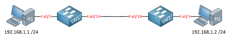
Above, you can see the topology of the computer connected to each switch. We put the computer in the same VLAN and create a relay between the two switches.
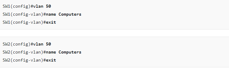
Let’s start by creating a VLAN:
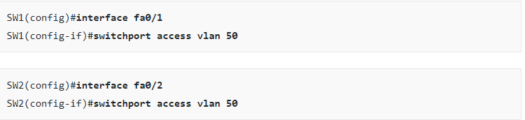
And let’s put the interfaces connected to the computers in the correct VLAN:
The next step is to create a relay between the two switches. Technically, the interface between the two switches can now be in access mode because I only have one VLAN.
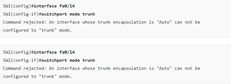
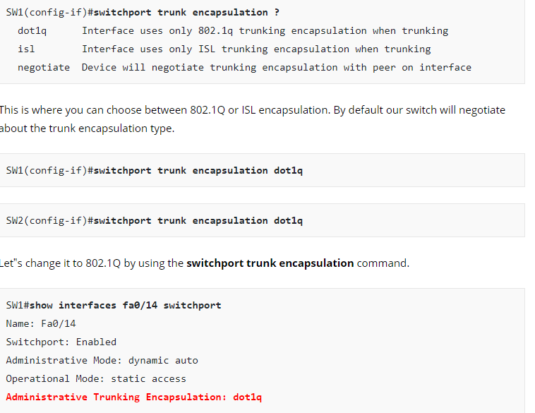
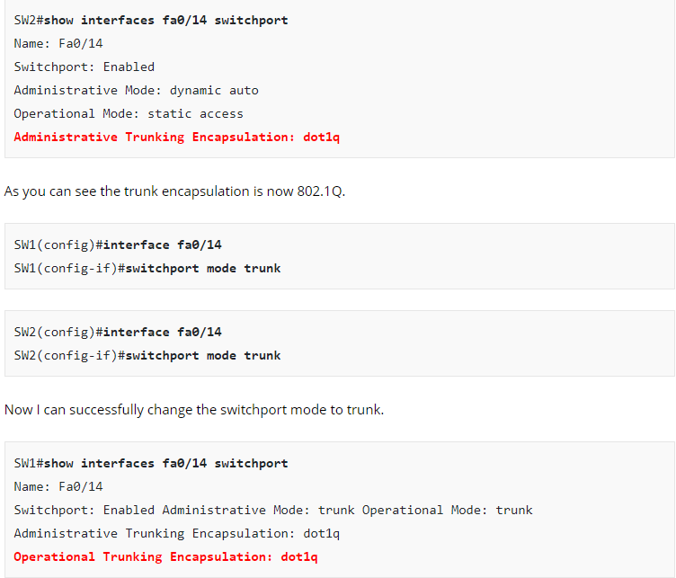
I tried to change the interface to trunk mode using the switchport mode trunk command. Depending on the switch model, you may see the same error as me. If we want to change the interface to trunk mode, we need to change the trunk encapsulation type. Let’s see what options we have:
Excellent! H1 and H2 can reach each other! Does this mean we are done? Not quite yet…there is more I want to show to you:
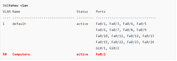
First, if we use the show vlan command, we can’t see the Fa0 / 14 interface. This is completely normal because the show vlan command displays only the interface in access mode and there is no relay interface.
The show interface trunk command is very useful. You can see if the interface is in relay mode, which relay encapsulation protocol (802.1Q or ISL) it is using and what the native VLAN is. We can also see that VLAN 1-4094.
We can also see that only VLAN 1 (local VLAN) and VLAN 50 are currently active. Last but not least, you can see which VLAN is in the forwarding state of the build tree.
I want to show you one more thing about access and trunk interfaces:
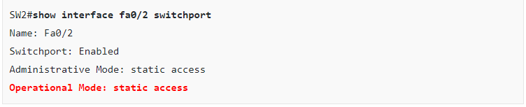
The interface can be in access mode or relay mode. The interface above is connected to H 2, and you can see that the mode of operation is static access, which means it is in access mode. This is our relay interface, which is connected to SW1.
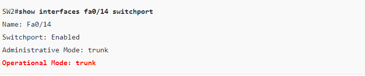
You can see that the mode of operation is backbone mode.
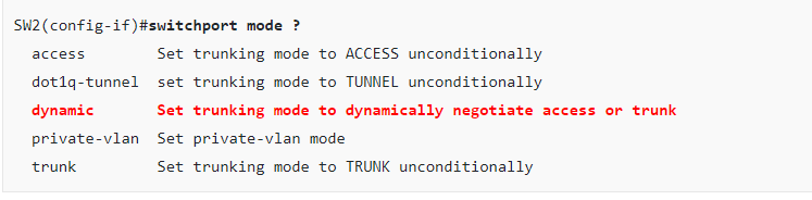
If I go to the interface configuration to change the switchport mode, you can see that I have more options than access or relay mode. There is also a dynamic approach. Don’t worry about other options for now.
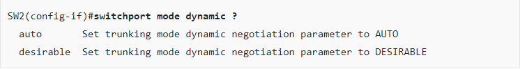
We can choose between dynamic automation and dynamics. Our switch will automatically find out whether the interface should be an access port or a relay port. So what is the difference between dynamic automation and dynamics? Let’s take a look!

hi, Bro, if you are interested in the article, and want to get more the relative contents. you can follow SPOTO, and you can improve your ability to take the Cisco certification exam
More you may be interested:
1. How to Configure VLANs on Cisco Catalyst Switch
2. Cisco Switch Virtualization