In a previous blog, I explained the campus network design and how we used different layers and "switch blocks" to create a layered design with redundant links.
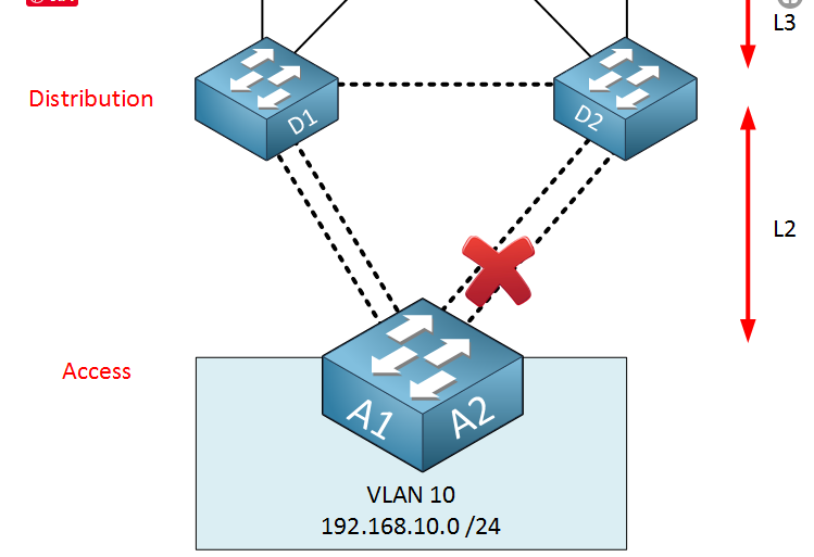
You also learned how spanning-tree can create a loop-free topology by blocking some redundant links. The "thing" about spanning trees is that we have a loop-free topology, we have redundancy, but we can't use all the redundant links to forward. This is a visual illustration:

The dotted line is the layer 2 link. The spanning-tree blocks two of these links to create a loop-free topology. Another problem with this topology is that we do have redundancy in the distribution (and core) layer, but we do not have redundancy in the access layer
When one of the distribution layer switches fails, the other can take over. We don't have that luxury at the access level... When one switch fails, the other cannot take over.
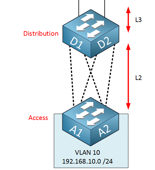
One way to solve this problem is to create logical switches. Cisco switches offer techniques for converting two or more physical switches into a single logical switch that looks like this:

A1 and A2 are two physical switches, but they combine into one logical switch. Distributed layer switches think they are connected to an access layer switch. An uplinking pair of switches at each distribution layer may be combined into an Ethernet channel.
When the link between D1 and D2 is a layer 2 link, the spanning tree must still block one of the Ethernet channels.
We can improve this topology by performing the same operations in the distribution layer, combining two physical distribution layer switches into one logical switch:

Note: if you are interested in the Switch Virtualization technology, and you can follow SPOTO. we will update more technical blogs to help your cisco certification exams.
More you may be interested:
1. Static MAC Address Table Entry
2. Top 5 IT Certification for Networking Engineers 2019

 Join Telegram Study Group ▷


