 Join Telegram Study Group ▷


802.1Q tunnel (also known as Q-in-Q) is a technology that Metro Ethernet providers often use as layer 2 VPN for customers. 802.1Q (or dot1q) tunnels are very simple. The provider will place 802.1Q tags on all frames received from customers with unique VLAN tags. By using different VLAN tags for each customer, we can separate traffic from different customers and transmit it transparently throughout the service provider network.
One advantage of this solution is that it is easy to implement, you don’t need foreign hardware, we don’t have to run any routing protocol between the service provider and customer (different from MPLS VPN). From the customer’s point of view, just like their website in layer 2 direct connection.
In this tutorial, I’m going to show you how to configure 802.1Q tunneling and I’ll explain how it works. I’ll be using the following topology for this:
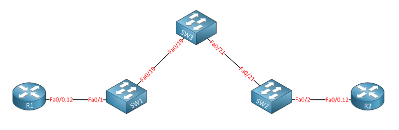
Above you see two routers called R1 and R2 and imagine that these routers are customer sites that we want to connect through a service provider network made up of SW1, SW2, and SW3. Our customers want to use VLAN 12 between the two sites and our service providers transfer them from one site to another.
In my example, our customers will use VLAN 12 to communicate between their sites. The service provider has decided to use VLAN 123 to transmit all content to the customer. This is basically what happens when we send frames between R1 and R2:
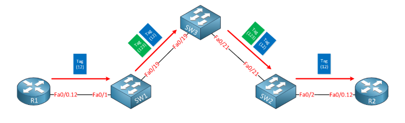
whenever r1 sends traffic, it marks its frames for vlan 12. Once it arrives at the service provider, SW1 will add an additional VLAN tag (123). Once SW2 forwards the frame to R2, it will remove the second VLAN tag and forward the original tag frame from R1.
Here is another way to visualize this:

Here’s what the router configs look like:
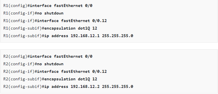
R1 and R2 are both configured with sub-interfaces and use subnet 192.168.12.0 /24. All their frames are tagged as VLAN 12.
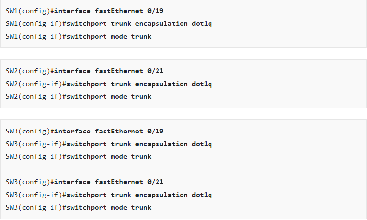
On the service provider network, we must configure a number of items. First, I will configure the 802.1Q trunk between SW1-SW3 and SW2-SW3:
The next part is where we configure the actual "Q-in-Q" tunnel. the service provider will use vlan 123 to transfer everything from our customers. We’ll configure a client-oriented router interface to tag everything about VLAN 123:

the switchportmodedot1q-tunnel command tells the switch to mark traffic and specifies the switch port access vlan command to specify q-in-qvlan as 123. ensure that vlan 123 is available on sw1, sw2, and sw3. By assigning the above interface to the VLAN, it is automatically created on SW1 and SW2, but I also have to make sure that SW3 has VLAN 123 in its database:

The show dot1q-tunnel command does not give me a lot of information. The only interface we’ve seen is the interface configured for the dot1q tunnel. By looking at the trunk between SW1, SW2, and SW3, it is proven that the service provider switch is actually a good way to transport the frame from the client tunnel:
Note: if you are interested in the article, and you can follow SPOTO to get more details of the technology. what's more, SPOTO will help you to pass various certification exams.

More you may be interested:
1. Cisco DTP (Dynamic Trunking Protocol) Negotiation
2. How to Configure Trunk on Cisco Catalyst Switch
3. How to Configure VLANs on Cisco Catalyst Switch