 Join Telegram Study Group ▷


In our previous blog post, we discussed the advantages and fundamentals of BGP / MPLS L 3 VPN. We have introduced the definition of basic terms, such as routing identifiers (RD), routing destination (RT) and VPN-IPv4 prefix. This article goes further. We will support the theory behind BGP / MPLS L 3 VPN through the actual configuration.
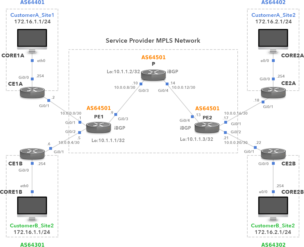
Our lab network consists of PE1, PE2 and P routers, which are part of the MPLS network of service providers. There are two remote sites: 1 (using CustomerA_Site1 and CustomerB_Site1) and 2 (using CustomerA_Site2 and CustomerB_Site2) to connect to the service providers MPLS network. Our goal is to interconnect remote customer sites so that they can communicate privately through shared media. This is where BGP / MPLS VPN comes in handy, using a combination of VRF, MPLS, and MP-BGP to separate traffic from two customers.
Customers use private addresses within their routing domains, which overlap with each other. For example, two customers use the same prefix 172.16.1.0 / 24 for site 1 and 172.16.2.0 / 24 for site 2.
IGP Configuration on P and PE routers
First, we will configure the IGP protocol between all P and PE routers to support LDP and BGP adjoining in the provider network. Even IGP or static routing may be an option. We can configure EIGRP because all the routers in our example coming from Cisco.
PE1(config)# router eigrp 1
PE1(config-router)# network 10.0.0.8 0.0.0.3
PE1(config-router)# network 10.1.1.1 0.0.0.0
P(config)# router eigrp 1
P(config-router)# network 10.0.0.8 0.0.0.3
P(config-router)# network 10.0.0.12 0.0.0.3
P(config-router)# network 10.1.1.2 0.0.0.0
PE2(config)# router eigrp 1
PE2(config-router)# network 10.0.0.12 0.0.0.3
PE2(config-router)# network 10.1.1.3 0.0.0.0
eBGP Configuration On Customer Routers
Now let’s configure the eBGP adjacency between CE and PE routers. The BGP AS number for each customer site must be unique and different from the provider’s ASN. For example, the customer A BGP AS number is 64401 at site 1 and ASN 64402 at site 2. We also use the following network command to route each customer’s subnet from CE to the PE router:
CE1A(config)# router bgp 64401
CE1A(config-router)# neighbor 10.0.0.1 remote-as 64501
CE1A(config-router)# network 172.16.1.0 mask 255.255.255.0
CE2A(config)# router bgp 64402
CE2A(config-router)# neighbor 10.0.0.17 remote-as 64501
CE2A(config-router)# network 172.16.2.0 mask 255.255.255.0
CE1B(config)# router bgp 64301
CE1B(config-router)# neighbor 10.0.0.5 remote-as 64501
CE1B(config-router)# network 172.16.1.0 mask 255.255.255.0
CE2B(config)# router bgp 64302
CE2B(config-router)# neighbor 10.0.0.21 remote-as 64501
CE2B(config-router)# network 172.16.2.0 mask 255.255.255.0
Configuring MP-BGP on PE Routers
Multi-protocol BGP is explained in RFC 4760 It defines the extension of BGP-4 so that it can carry routing information for multiple network layer protocols (for example, IPv6,L3VPN). Therefore, we will configure MP-BGP to distribute the customerundefineds prefix. The extension is backward compatible. Routers that support extension can interoperate with routers that do not support extension.
iBGP neigborship is formed between the PE routers, using ASN 64501.
No BGP is configured on router P.
PE1(config)# router bgp 64501
PE1(config-router)# neighbor 10.1.1.3 remote-as 64501
PE1(config-router)# neighbor 10.1.1.3 update-source lo0
PE1(config-router)# address-family vpnv4
PE1(config-router-af)# neighbor 10.1.1.3 activate
PE1(config-router-af)# exit
Note: The command neighbor 10.1.1.3 send-community extended is automatically configured under the address-family vpnv4 section.

PE2(config)# router bgp 64501
PE2(config-router)# neighbor 10.1.1.1 remote-as 64501
PE2(config-router)# neighbor 10.1.1.1 update-source lo0
PE2(config-router)# address-family vpnv4
PE2(config-router-af) # neighbor 10.1.1.1 activate
PE2(config-router-af)# exit
Note: The command neighbor 10.1.1.1 send-community extended is automatically configured under the address-family vpnv4 section.
Enable MPLS on PE and P Routers
We need to enable MPLS in a provider’s network. Customers’ data are then switched in the MPLS network based on the outer (LSP) label. We will enable MPLS on a provider’s P router and on PE routers.
PE1(config)# interface GigabitEthernet 0/3
PE1(config-if)# Mpls IP
P(config)# interface GigabitEthernet 0/3
P(config-if)# Mpls IP
P(config)# interface GigabitEthernet 0/4
P(config-if)# Mpls IP
PE2(config)# interface GigabitEthernet 0/4
PE2(config-if)# Mpls IP
Create and Assign VRFs
The client’s forwarding table is separated by the VPN routing and forwarding table(VRF)concept on the PE router. One VRF per customer is configured on the PE router. Then, the router PE interface that connects the CE router to the provider’s MPLS network is assigned to the customer VRF.
The routing recognizer adds a prefix to the customer on the PE router to distinguish the same prefix and mask in different VRF. For example, PE1 routers declare prefixed RD1:172.16.10 / 24 and RD2:172.16.1.0/24 and VPN tags to PE2 routers in BGP update messages. RD is used to distinguish prefixes and does not affect how routes are installed in VRF. The routing target is extended community property for VPN routing import/export. For example, the VPN prefix 172.16.1.0 / 24, sent from PE1 to PE2 within the PE-BGP update message and carrying the routing target 64501 / 1, is imported to the VRF customer on PE2.
PE1(config)# IP vrf CustomerA
PE1(config-vrf)# rd 64501:1
PE1(config-vrf)# route-target both 64501:1
Note: the commands route-target export 64501:1 and route-target import 64501:1 are automatically configured under vrf configuration.
PE1(config-vrf)# ip vrf CustomerB
PE1(config-vrf)# rd 64501:2
PE1(config-vrf)# route-target both 64501:2
Note: the commands route-target export 64501:2 and route-target import 64501:2 are automatically configured under vrf configuration.
Now we need to assign L3 interfaces to customer VRF.
PE1(config)# interface gigabitEthernet 0/1
PE1(config-if)# ip vrf forwarding CustomerA
PE1(config-if)# IP address 10.0.0.1 255.255.255.252
PE1(config)# interface gigabitEthernet 0/2
PE1(config-if)# ip vrf forwarding CustomerB
PE1(config-if)# IP address 10.0.0.5 255.255.255.252
We will create the same VRFs on PE2 and assign interfaces to VRFs.
PE2(config)# IP vrf CustomerA
PE2(config-vrf)# rd 64501:1
PE2(config-vrf)# route-target both 64501:1
PE2(config-vrf)# IP vrf CustomerB
PE2(config-vrf)# rd 64501:2
PE2(config-vrf)# route-target both 64501:2
PE1(config)# interface gigabitEthernet 0/1
PE1(config-if)# ip vrf forwarding CustomerA
PE1(config-if)# IP address 10.0.0.17 255.255.255.252
PE1(config)# interface gigabitEthernet 0/2
PE1(config-if)# ip vrf forwarding CustomerB
PE1(config-if)# IP address 10.0.0.21 255.255.255.252
Configure eBGP towards Customers on the PE Routers
So far, we have configured eBGP on the customers’ routers. However, we also need to define the BGP neighbors for the PE routers under the address-family ipv4 vrf section, in order to establish the BGP adjacencies with the CE routers.
PE1(config)# router BGP 64501
PE1(config-router)# address-family ipv4 vrf CustomerA
PE1(config-router-af)# neighbor 10.0.0.2 remote-as 64401
PE1(config-router-af)# exit
PE1(config-router)# address-family ipv4 vrf CustomerB
PE1(config-router-af)# neighbor 10.0.0.6 remote-as 64301
PE2(config)# router BGP 64501
PE2(config-router)# address-family ipv4 vrf CustomerA
PE2(config-router-af)# neighbor 10.0.0.18 remote-as 64402
PE2(config-router-af)# exit
PE2(config-router)# address-family ipv4 vrf CustomerB
PE2(config-router-af)# neighbor 10.0.0.22 remote-as 64302
Inspecting the Forwarding Plane
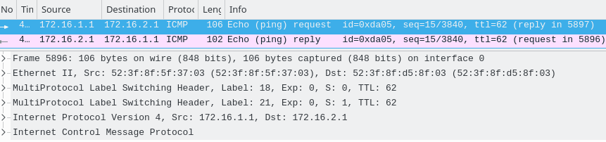
Figure 2 shows the traffic captured on the link between the PE1 and the P router, while at the same time from PC1A ping to PC2B. The outer MPLS label exchange path (LSP) is 18, which is used for label exchange. It is learned through LDP (Label Distribution Protocol) and has local significance.
The MPLS forwarding table for PE1 is shown in figure 3.
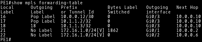
Tag 21 is an internal (VPN) tag added by the PE1 router. It is used to identify the correct next-hop (10.0.0.18) for client A data traffic on the PE2 router. The internal label remains unaffected by the P router. Only PE routers perform push or pop-up of VPN tags. The VPN tag for customer B traffic is 22. 5%.
The P router is a transport router that performs the pop-up of LSP tags 18 and 19 (figure 4). This router makes forwarding decisions based only on labels. Tag 19 is the LSP tag pushed by the PE2 router when it sends traffic to 10.1.1.1.
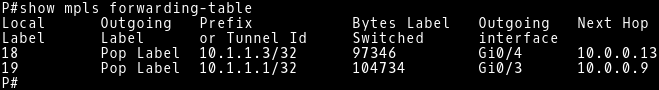
FIG.5 depicts the traffic captured on the link between the P and PE2 routers while the ping command is sent from the PC1A to the PC2B. There is only one mpls header with the VPN label 21 because the p router has added the tag 18. The router PE2 deletes the internal VPN header 21 and forwards the ICMP request as a normal IP message to the CE2A (10.0. 0.18).
In the opposite direction, packets with ICMP echo messages from PC2A to PC1A contain LSP tags in the MPLS header. The VPN tag is the same as in the echo request (21) because both sides are customers A. Figure 6 describes the MPLS forwarding table for PE2 routers.
Figure 7 illustrates the forwarding table of the PE2 router for VRF client A. It contains two routes learned through BGP. The route 172.16.2.0 / 24 published by the client router CE2A and the route 172.16.1.0 published by the router PE1.
Inspecting Control Plane
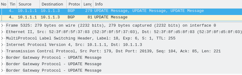
The BGP update message sent from pe1 to pe2 is shown in fig.8. Note that only one mpls header with LSP label 18 is missing and a VPN label is missing. It ensures that the mp-BGP message is sent over the Mpls network. The VPN label is distributed in the MP-BGP update message along with a unique VPN-IPv4 prefix.
VPN-IPv4 routing is the customer's route, which is modified to be unique to use the same private IP address for the customer. VPN-IPv4 routing identifiers (RD) and prefixes are composed of routing identifiers and prefixes. Figure 9 shows the contents of NLRI in the MP_REACH_NLRI path property. It is the prefix 172.16.1.0, Rd 64501 ≤ 2 and the tag stack (VPN tag) 22 (customer B).
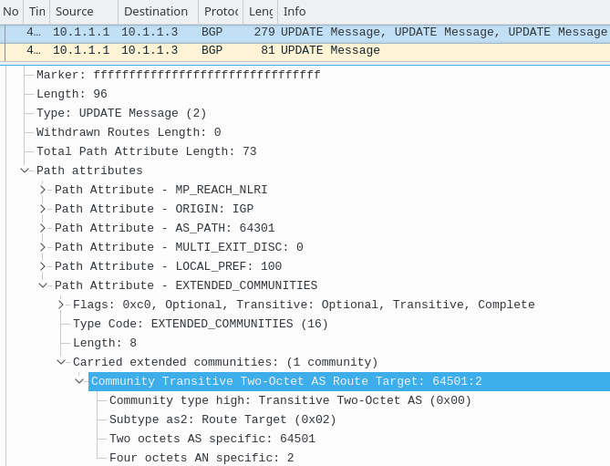
The BGP update message also contains the path property EXTENDED_COMMUNITIES. where the path target 64501 / 2 is located As shown in figure 10.
Conclusion:
We provide the exact configuration steps to help our readers create BGP/ MPLS L3 VPN and master the overall concept. Read our first blog post if you need more theoretical knowledge about the BGP/ MPLS VPN concept. If you need a Cisco MPLS configuration step by step tutorial, please click the hypelink.
About SPOTO
SPOTO focus on online IT Certification training for 16 years. SPOTO offers 100% real and valid Cisco CCNA, CCNP, CCIE, ISC, Amazon AWS, Microsoft, and other IT exam practice tests. And we have many free online training courses of Cisco exam on YouTube. You can find many useful and helpful tips and suggestions. If you’re still worried about to prepare and pass the Cisco exam, try SPOTO now. SPOTO tutors will help you get the CCIE number at the first try. we will provide the tutorial video about the MPLS and BGP.