 Join Telegram Study Group ▷


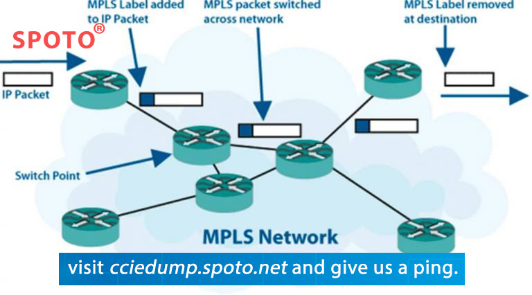

If you are looking for an MPLS tutorial or a step-by-step Mpls configuration example, this basic MPLS VPN configuration example will guide you to configure the first router as a 3-router MPLS core with two external sites.
If you‘re looking for an explanation for MPLS, I suggest you read "What is MPLS" before trying this experiment. Route distinguisher, vpn routing, static routes, ce routers, address family ipv4 vrf, router id,
router bgp,
ip routing,
route target import,
route target export,
loopback interface,
import and export,
loopback address
Cisco MPLS configuration video above that introduces the whole tutorial, so if you just want to watch the video there and want to continue learning, it is recommended that you open this page twice or print it out for taking notes.
which building a simple Mpls topology will include a 3 router Mpls core and two remote sites in the vrf running OSPF (as a pe-ce routing protocol). this is a long article as I will take you through each validation throughout to make sure you understand how each part works.
I will use SPOTO's equipment and configure the router so you can continue. I've also started to dabble in web automation - if you need more, check out my pages on Ansible for Network Engineers.
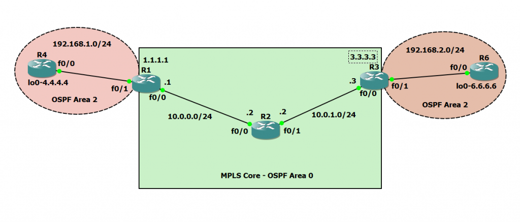
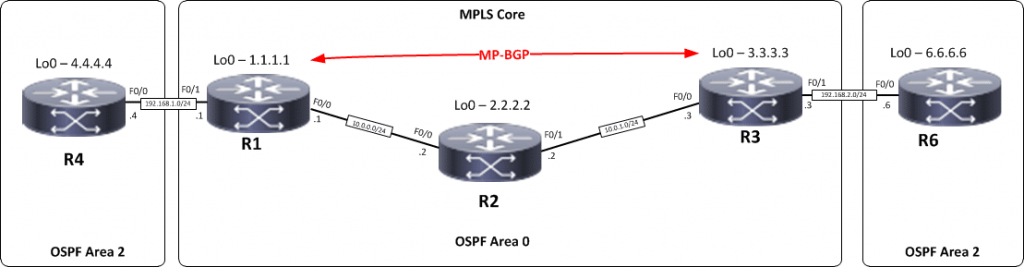
Cisco MPLS Tutorial Topology
Step 1– IP addressing of MPLS Core and OSPF
First put 3 routers into topology R1, R2, R3, as shown below.
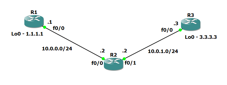
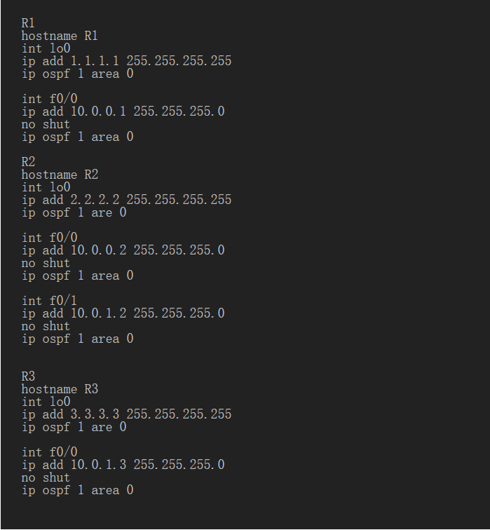
we will solve the router problem and configure the OSPF to ensure the loopback connection between r1 and r3.
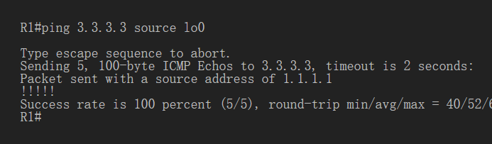
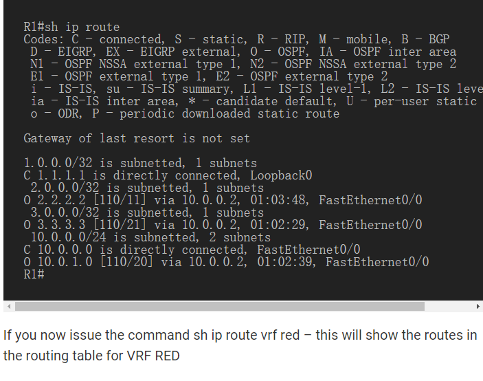
Now that you should have a full IP connection between R1, R2, R3 to verify this, we need to see if we can doping between R1 and R3 loops You can display the routing table here, but the fact that you can perform ping between loopbacks is sufficiently verified and can proceed.
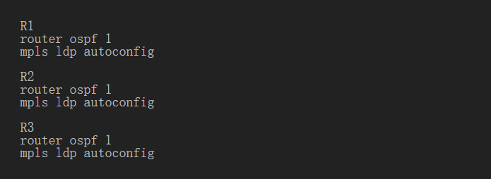
Step 2– Configure LDP on all interfaces in MPLS Core
In order to run MPLS, you need to enable it, there are two ways to implement it.
1. Enter the mpls ip command on each interface Under the OSPF process
2. Use the mplsldpautoconfig command in this tutorial, we will use the second option, so go to the OSPF process and enter mplsldpautoconfig – this will enable the Mpls label distribution protocol on each interface that runs the OSPF under that particular process.
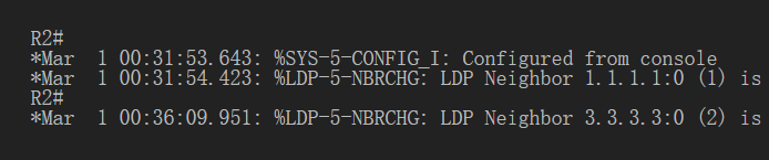
You should see a log message that shows that the LDP neighbor has started.
To validate the Mpls interface, the command is a very simple - sample interface.
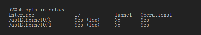
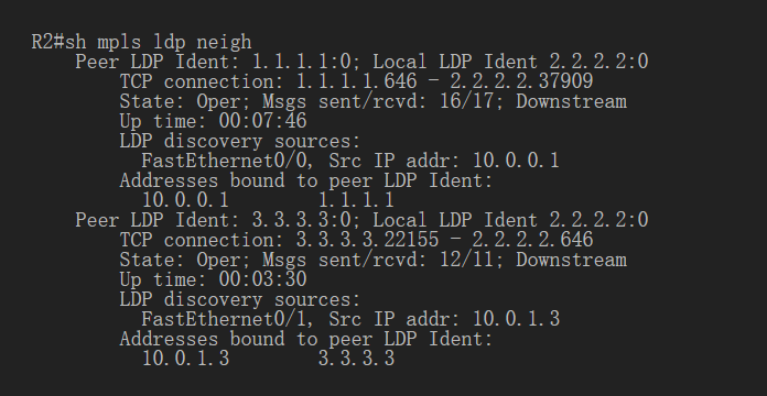
This is done on R2 and you can see both interfaces running Mpls and using LDP you can also use the shmplsldpneighbors command to verify the LDP neighbors.
Another verification method to confirm whether LDP can run normally is to track between R1 and R3 and to verify whether to display MPLS labels in the tracking.
As you can see, the trace to R2 used the MPLS tag in the path as this is a very small MPLS core and only one tag was used as R3 is the last hop.
Therefore, review that we have now configured IP addresses on the Mpls core, enabled OSPF and full IP connections between all routers, finally enabled Mpls on all interfaces in the core, and established LDP neighbors between all routers.
The next step is to configure MP-BGP between R1 and R3 This is when you start seeing the Layer 3 VPN configuration take effect.
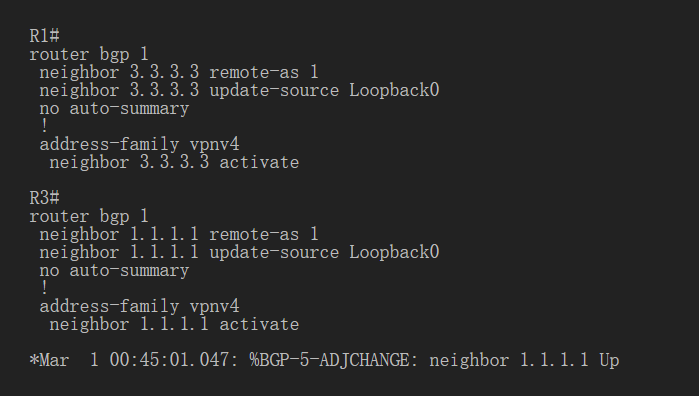
Step 3– MPLS BGP configuration between R1 and R3
We need to establish a multi-protocol BGP session between R1 and R3, which is done by configuring the vpnv4 address family as follows You should see a log message showing the upcoming BGP session.
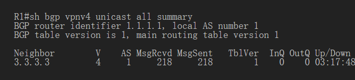
To verify the BGP session between R1 and R3, issue the command sh bgp vpnv4 unicast all summary you can see here that we do have a bgpvpnv4 with r3 peer – look at pfxrcd and you will see that it shows 0 because there is no routing in the BGP.
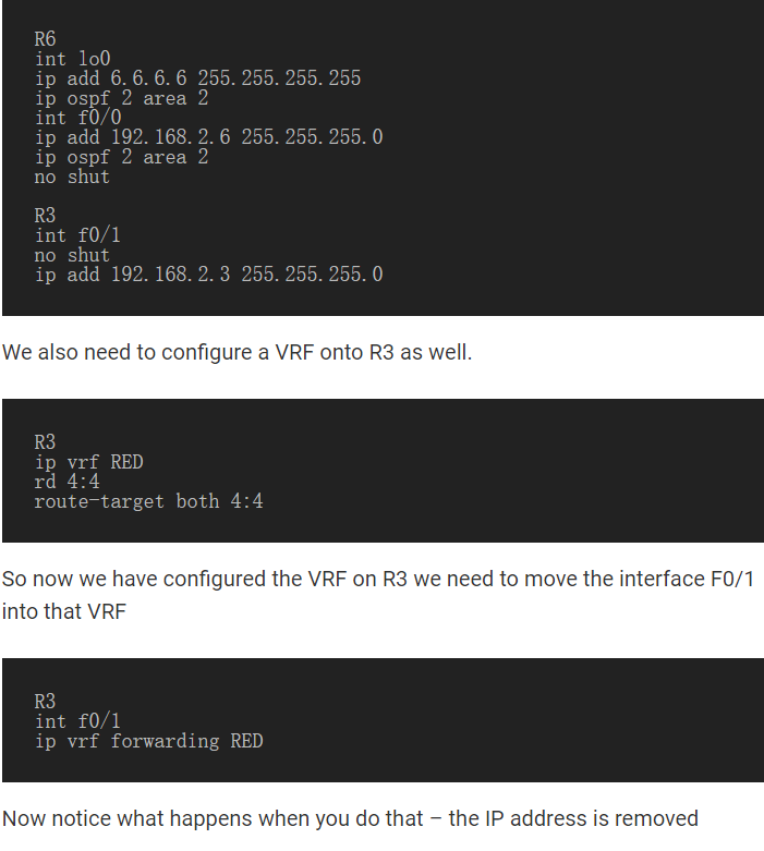
now we will add two more routers in the topology. These will be customer sites connected to R1 and R3. We will then create a VRF on each router and put the interface connected to each site router into that VRF.
Step 4- Add two more routers to create the VRF
We’ll add two more routers to the topology, so now it looks like the final topology
Router 4 will use the VRF configured on process number 2 equal OSPF to R1.
it will use local address 192.168.1.0/24. Now, we can peer R4 to R1, but in the global routing table of R1, this is not what we want.
Now, we’re going to start using the VRF. What is VRF in the network? virtual routing and forwarding (vrf) is a technique included in IP (internet protocol) that allows multiple instances of routing tables to coexist in routers and work together without interfering with each other.
This increases functionality by allowing network paths to be subdivided without using multiple devices.
For example, if R1 is an ISP’s PE provider edge router and both customers use 192.168.1.0/24 address space to address locally, it can accommodate both routing tables in different VRFs – distinguish between two they use routing recognizers
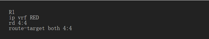
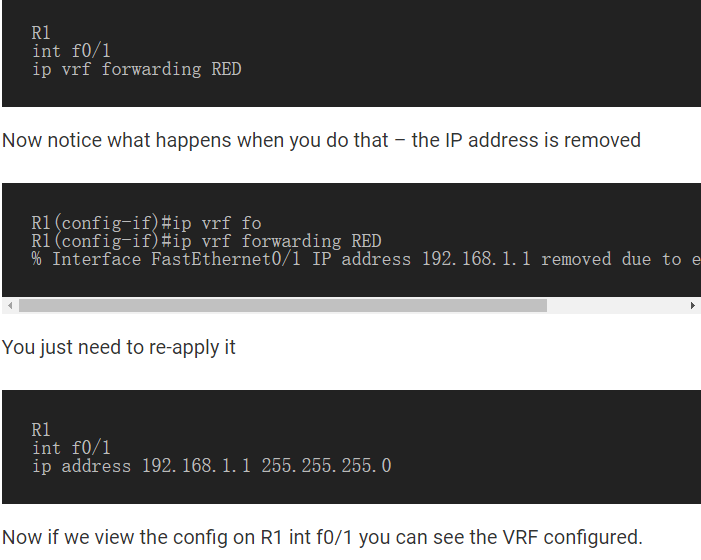
Back to topology - we now need to create VRF on R1 For this MPLS tutorial, I will use VRF RED
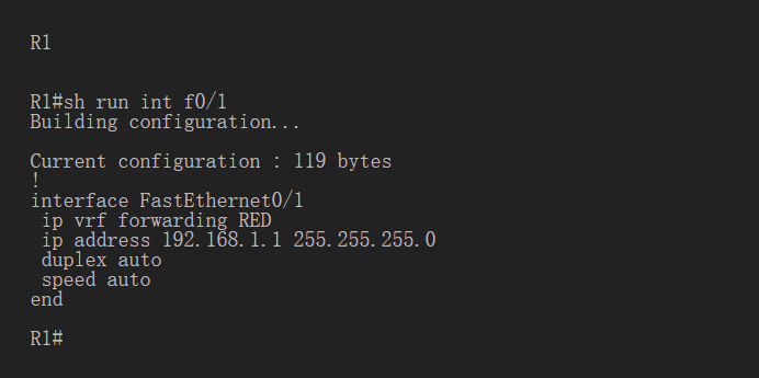
RD and route objectives need not be the same - for complete instructions, read this article about Route Distributing uishers Before proceeding, identify the route recognizer and route-target. Now we have VRF configured on R 1.
Note: if you want to know more technical topics, and you can follow SPOTO where we can update various IT technology that are beneficial for your cisco certification exams. what's more, you can contact us directlyif you have any questions.
Besides, we have Youtube and Facebook Live 22:30-23:30 GMT+8, which focuses on BGP technology. if you are interested in that, and you can follow us:

More Related Topics
2. 5 Best Cisco Certifications in Demand
3. How to advertise networks in BGP