 Join Telegram Study Group ▷


Layer 2 switching (or data link layer switching) is the process of dividing the network using the MAC address of the device on the LAN. Switches and bridges are used for layer 2 switching. They decompose a larger collision domain into several smaller collision domains.
In a typical LAN, all hosts are connected to a central device. In that past, the device is typically a hub. But the hub has a number of disadvantages, such as not knowing the traffic through them, creating a large collision domain, and the like. To overcome some of the problems of the hub, a bridge is created. They are better than hubs because they create multiple conflict domains, but the number of ports is limited. Eventually, the switch was created and is still widely used. The switch has more ports than the bridge to check incoming traffic and make corresponding forwarding decisions. each port on the switch is a separate collision domain.
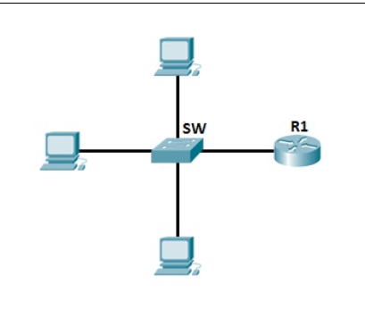
This is an example of a typical LAN network used today as a central device that connects all devices together:
Differences between hubs and switches
To better understand the concept of packet switching based on device hardware addresses, you need to know the difference between the switch and the hub.
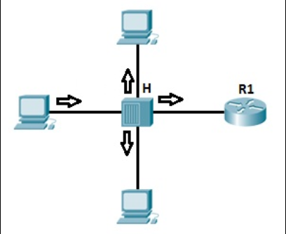
First, consider the example of a LAN, with all hosts connecting to a hub:
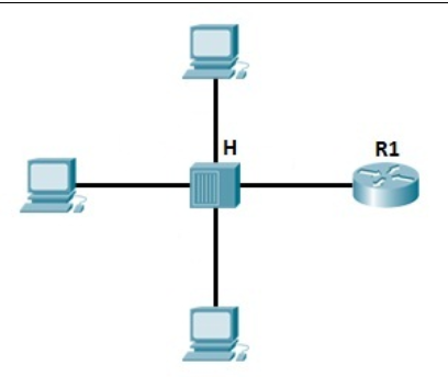
As mentioned earlier, the hub only creates a collision domain, so the chance of a collision is high. The hub described above is only a signal that repeatedly receives all of the ports except the port from which the signal is received, so packet filtering is not performed. Imagine if there are 20 hosts connected to the hub, a packet will be sent to 19 hosts, not just one! This can also lead to security problems, as an attacker can capture all traffic on the network.
The mode of operation of the switch is now considered.
We have the same topology as above, but we’re using the switch instead of the hub.
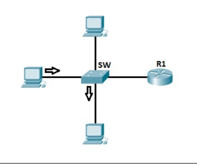
The switch increases the number of collision domains. Each port is a collision domain, meaning that the chance of a collision is small. The switch knows which port to connect to and forwards the frame based on the destination MAC address included in the frame. This reduces traffic on the LAN and enhances security.
How switches work
Each network card has a unique identifier called the Media Access Control (MAC) address. The address is used in a LAN for communication between devices on the same network segment. The devices that want to communicate the need to know the mac address to each other before sending the data packets. They use the process called ARP (Address Resolution Protocol) to find the MAC address of another device. When the hardware address of the target host is known, the sending host has all the information needed to communicate with the remote host.
To better understand the concept of ARP, let’s take a look at the following example:
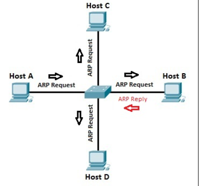
Suppose host A wants to communicate with host B for the first time. Host A knows the IP address of host B, but because this is the first communication between the two hosts, the hardware (MAC) address is not known. Host A uses the ARP process to find the MAC address of host B. The switch forwards the ARP request to all ports except the port to which host A is connected. Host B receives the ARP request and responds with its MAC address. Host B also learns the MAC address of host A (because host A sends its MAC address in the ARP request). The switch knows which MAC addresses are associated with which port. For example, because host B responds with an ARP response that contains its MAC address, the switch knows the MAC address of host B and stores the address in its MAC address table. As with host A, the switch knows the MAC address of host A because of the ARP request.
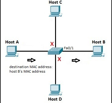
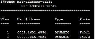
Now, when host A sends a packet to host B, the switch looks up in its MAC address table and forwards the frame only to the Fa0/1 port (port connected to host B). Other hosts in the network will not participate in the communication:
You can display the MAC address table of the switch by using the show mac-address-table command:
NOTE: if you are interested in the blog, and you can follow SPOTO where we will update more technical articles related to Cisco certification exams.

More Recommended Articles
1. FAQ of Purchasing/Scheduling Cisco Online Exams
2. Wow! SPOTO New CCIE LAB Policy is Coming!
3. The Explanation of HTTP and HTTPS