

A VRF is a second routing table with its own forwarding table, its own protocol instances, and no relationship to any other. That isolation is the entire point and it is also the entire problem, because networks that separate traffic for policy reasons almost always need a controlled exception somewhere — shared services, internet access, a management path. Route leaking is the name for those exceptions, and it is harder than it looks because the mechanism that keeps two tables apart has no natural notion of "except this".
The confusion starts with terminology. VRF-Lite means VRFs without MPLS: each device holds separate tables and each link between devices carries separate sub-interfaces or separate physical links, one per VRF. MPLS L3VPN means VRFs plus MP-BGP plus a labelled core, where the separation is carried across the network by labels and the VRFs exist only at the edges. The configuration of the VRF itself is nearly identical; what differs is how the separation travels between devices, and therefore how many interfaces the design consumes and what leaking mechanisms are available.
This article covers both and the leaking. Section one distinguishes VRF-Lite from L3VPN and explains what a VRF actually separates. Section two is configuration — the two syntaxes, interface assignment, and running routing protocols inside a VRF. Section three covers leaking between VRFs, with the four mechanisms and when each applies. Section four covers the global table, which behaves differently enough to need its own treatment. Section five is the failure catalogue, starting with the command that silently removes every IP address on an interface.
vrf forwarding removes the interface's IP address without warning, which makes the single most common VRF mistake a self-inflicted outage during the change that was supposed to create the separation.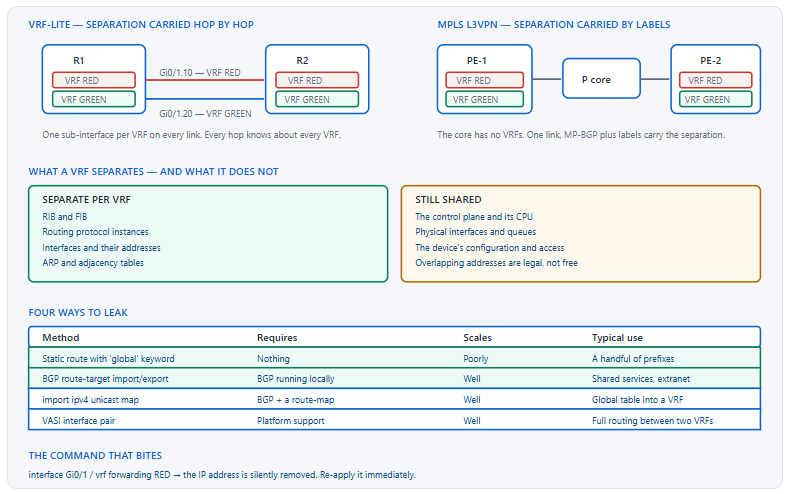
What Is a VRF and How Does VRF-Lite Differ from MPLS L3VPN?
What does a VRF actually separate?
A VRF gives you a separate routing table, a separate forwarding table, separate ARP and adjacency state, and the ability to run separate instances of routing protocols. Interfaces belong to exactly one VRF, and two VRFs may use overlapping address space because the tables never meet. What a VRF does not separate is the device itself: one control plane, one CPU, one set of physical interfaces and queues, and one configuration that an operator with access can change for every VRF at once. A VRF is a routing separation, not a security boundary in the sense a separate device would be.
A Deeper Dive into VRFs and the Two Deployment Models
VRF-Lite versus MPLS L3VPN
| Property | VRF-Lite | MPLS L3VPN |
|---|---|---|
| Separation between devices | One sub-interface or link per VRF | Labels over a shared core |
| Core devices need VRF configuration | Yes — every hop | No — the core is VRF-free |
| Interfaces consumed | Grows with VRF count | One per PE-CE attachment |
| MP-BGP required | No | Yes |
| Route Distinguisher required | Only if BGP is used | Yes |
| Scales to how many VRFs | A handful before it becomes unmanageable | Thousands |
| Typical use | Campus segmentation, a few tenants, a lab | Provider VPN service, large enterprise segmentation |
The VRF definition itself is identical in both. What changes is everything around it: VRF-Lite propagates separation by having a distinct Layer 3 path per VRF at every hop, which is straightforward and consumes an interface per VRF per link. L3VPN propagates it with MP-BGP and labels, which requires more machinery and then scales essentially without limit.
The two configuration syntaxes
The legacy syntax, ip vrf NAME, supports IPv4 only. The modern multiprotocol syntax, vrf definition NAME, has an address family per protocol and is required for IPv6. Current platforms accept both, and mixing them across a network is a source of confusion because the interface command differs — ip vrf forwarding for the legacy form and vrf forwarding for the modern one. A conversion command exists and should be used to standardise.
! ===== Legacy syntax, IPv4 only =====
ip vrf RED
 rd 65000:100
 route-target export 65000:100
 route-target import 65000:100
!
interface GigabitEthernet0/1
 ip vrf forwarding RED
!
! ===== Modern multiprotocol syntax =====
vrf definition RED
 rd 65000:100
 address-family ipv4
  route-target export 65000:100
  route-target import 65000:100
 exit-address-family
 address-family ipv6
  route-target export 65000:100
  route-target import 65000:100
 exit-address-family
!
interface GigabitEthernet0/1
 vrf forwarding RED
!
! Convert a legacy VRF in place
R1(config)# vrf upgrade-cli multi-af-mode common-policies vrf RED
The Route Distinguisher, which is not a policy tool
An RD is eight bytes prepended to an IPv4 prefix to make it unique across VRFs, so that two customers both using 10.0.0.0/8 produce two distinct VPNv4 prefixes. It is part of the NLRI, not an attribute, and it controls nothing about who receives a route. Route Targets do that. In pure VRF-Lite with no BGP, an RD is not strictly required at all — it becomes necessary the moment BGP carries the VRF's prefixes.
! RD makes the prefix unique; RT decides who imports it
vrf definition RED
 rd 65000:100          ! uniqueness only
 address-family ipv4
  route-target export 65000:100   ! policy
  route-target import 65000:100   ! policy
 exit-address-family
!
! Two VRFs with the same address space, distinguished by RD
R1# show bgp vpnv4 unicast all | include Route Distinguisher|10.0.0.0
Route Distinguisher: 65000:100 (default for vrf RED)
 *> 10.0.0.0/8   172.16.1.2   0   0 65100 i
Route Distinguisher: 65000:200 (default for vrf GREEN)
 *> 10.0.0.0/8   172.16.2.2   0   0 65200 i
vrf definition costs nothing extra and removes the eventual migration when IPv6 arrives. Mixing the two syntaxes across a network means two different interface commands and two different mental models for the same object, which is a recurring source of small errors during changes.When VRF-Lite stops being the right answer
VRF-Lite costs one logical interface per VRF per link, and one routing protocol instance per VRF per device. Three VRFs across a six-router ring is eighteen sub-interfaces and eighteen protocol instances, which is manageable. Eight VRFs across a thirty-router campus is a different proposition: the sub-interface count passes two hundred, every new VRF is a change on every device in the path, and a single missed sub-interface produces a black hole that only appears for one tenant.
The threshold worth watching is not the VRF count on its own but the product of VRF count and path length. Two VRFs across twenty hops is as much configuration as twenty VRFs across two hops, and the twenty-hop version is worse because the failure is harder to locate. Where that product starts climbing, either shorten the path the VRFs traverse — terminate them at a pair of aggregation devices and use a single routed core beyond that — or move to a label-carried design where adding a VRF touches only the two edges that need it.
How Do I Configure a VRF and Put Routing In It?
What is the order of operations?
Define the VRF, assign interfaces, re-apply the addressing, then configure routing. The middle step is the one that catches people: vrf forwarding removes the interface's IP address, because an address belongs to a table and moving the interface to a different table invalidates it. On a live interface that is an immediate outage lasting until the address is re-typed, which is why VRF assignment on production interfaces is done from a console or with the two commands prepared together as a block.
A Deeper Dive into Configuration
Interfaces and the addressing trap
! Apply these TWO lines together, never one at a time
interface GigabitEthernet0/1.10
 encapsulation dot1Q 10
 vrf forwarding RED
 ip address 172.16.1.1 255.255.255.0
! ^ Without the second line, the interface has no address at all.
!
! What it looks like if you forget
R1# show ip interface brief | include Gi0/1.10
GigabitEthernet0/1.10  unassigned  YES manual up   up
!
! Which interfaces are in which VRF
R1# show vrf
  Name         Default RD      Protocols   Interfaces
  RED          65000:100       ipv4,ipv6   Gi0/1.10
  GREEN        65000:200       ipv4,ipv6   Gi0/1.20
Routing protocols inside a VRF
Each protocol has its own way of expressing VRF membership. OSPF takes a vrf keyword on the process, and each VRF needs its own process ID. EIGRP uses an address family with a VRF name. BGP uses an address family under one process. Static routes take a vrf keyword on the command. Getting the VRF context wrong produces statements that are syntactically valid and operate on the global table.
! OSPF: one process per VRF
router ospf 100 vrf RED
 router-id 10.0.0.1
 network 172.16.1.0 0.0.0.255 area 0
!
! EIGRP named mode: an address family per VRF
router eigrp CORP
 address-family ipv4 unicast vrf RED autonomous-system 100
  network 172.16.1.0 0.0.0.255
  eigrp router-id 10.0.0.1
 exit-address-family
!
! BGP: an address family under the one process
router bgp 65000
 address-family ipv4 vrf RED
  neighbor 172.16.1.2 remote-as 65100
  neighbor 172.16.1.2 activate
  redistribute ospf 100 vrf RED match internal external 1 external 2
 exit-address-family
!
! Static: the vrf keyword on the command
ip route vrf RED 10.5.0.0 255.255.0.0 172.16.1.2
Verification is VRF-scoped too
Every show and every operational command needs the VRF named, or it operates on the global table. That includes the diagnostic tools — a ping without vrf sources from the global table and will fail against a VRF destination even when the VRF's routing is perfect, which produces a false negative that sends people looking for a routing problem that does not exist.
! Every command needs the VRF, or it reads the global table
R1# show ip route vrf RED
R1# show ip route vrf RED 10.5.0.0
R1# show ip cef vrf RED 10.5.0.1
R1# show ip protocols vrf RED
R1# show ip ospf 100 neighbor
R1# show bgp vpnv4 unicast vrf RED
!
! Diagnostics too - this is the false-negative source
R1# ping vrf RED 10.5.0.1
R1# ping vrf RED 10.5.0.1 source 172.16.1.1
R1# traceroute vrf RED 10.5.0.1
!
! Without the keyword, this uses the global table and fails
R1# ping 10.5.0.1
% Network unreachable
! ^ Correct behaviour. The destination is not in the global table.
Management access from a VRF
Where the management interface sits in a VRF — a common design — the services the router originates need to be told. SSH, TACACS, syslog, NTP, SNMP, and DNS each take a VRF specification, and each defaults to the global table. A device whose management interface moved into a VRF without these changes remains reachable inbound and loses every outbound service.
! Management in a dedicated VRF
vrf definition MGMT
 address-family ipv4
 exit-address-family
!
interface GigabitEthernet0
 vrf forwarding MGMT
 ip address 192.168.99.10 255.255.255.0
!
ip route vrf MGMT 0.0.0.0 0.0.0.0 192.168.99.1
!
! Every originating service needs telling
ip ssh source-interface GigabitEthernet0
ip domain lookup vrf MGMT
logging host 192.168.99.20 vrf MGMT
ntp server vrf MGMT 192.168.99.30
snmp-server host 192.168.99.40 vrf MGMT version 2c public
aaa group server tacacs+ TAC
 server-private 192.168.99.50 key 7 08351F1B
 ip vrf forwarding MGMT
 ip tacacs source-interface GigabitEthernet0
Dual-stack VRFs and the address-family split
The modern vrf definition syntax holds an IPv4 and an IPv6 address family in one VRF, and the two are configured independently. A VRF with only address-family ipv4 enabled will accept an IPv6 address on a member interface and then fail to route it, because the IPv6 table for that VRF does not exist. The route targets are also per-address-family, so an RT scheme that works for IPv4 does nothing for IPv6 until it is repeated under the IPv6 family.
! Both families, each with its own RTs
vrf definition RED
 rd 65000:100
 address-family ipv4
  route-target export 65000:100
  route-target import 65000:100
 exit-address-family
 address-family ipv6
  route-target export 65000:100
  route-target import 65000:100
 exit-address-family
!
interface GigabitEthernet0/1.10
 vrf forwarding RED
 ip address 172.16.1.1 255.255.255.0
 ipv6 address 2001:db8:1::1/64
!
! Verify each family separately - show vrf lists which are enabled
R1# show vrf detail RED | include Address family
Address family ipv4 unicast (Table ID 0x1):
Address family ipv6 unicast (Table ID 0x1E000001):
!
R1# show ipv6 route vrf RED
vrf forwarding applied to a live interface Symptom: the interface goes down for routing purposes the instant the command is entered, every adjacency on it drops, and if it was the path to the router the session is lost mid-change. Cause: assigning an interface to a VRF invalidates its IP address, because the address belonged to the previous table. The address is removed silently and the interface has none until it is re-applied. Confirm: show ip interface brief shows the interface as unassigned. Fix: always enter vrf forwarding and ip address as a single pasted block, and never on the interface carrying your management session unless you have console access.vrf keyword the most common false negative in VRF troubleshooting.How Do I Leak Routes Between VRFs?
Which mechanism for which requirement?
Route Targets when BGP is available, which is nearly always the right answer: exporting a shared-services VRF's routes with one RT and importing that RT into every tenant VRF is a two-line policy that scales to any number of tenants. Static routes with a next hop in the other VRF where BGP is not running and the prefix count is tiny. A VASI interface pair where two VRFs need full dynamic routing between them and the platform supports it. And a physical loopback cable, which is a real answer in a lab and an admission of defeat in production.
A Deeper Dive into Leaking Between VRFs
Route Targets, which is the scalable answer
The mechanism is the same one that builds any L3VPN topology. A shared-services VRF exports its routes with a distinctive RT; every tenant VRF imports that RT in addition to its own. The tenants do not import each other's RTs, so they remain separated from one another while both reaching the shared services. Adding a tenant is one import line in the new VRF and no change anywhere else.
! ===== Shared services VRF =====
vrf definition SHARED
 rd 65000:900
 address-family ipv4
  route-target export 65000:900
  ! Import each tenant so return traffic works
  route-target import 65000:100
  route-target import 65000:200
 exit-address-family
!
! ===== Tenant RED =====
vrf definition RED
 rd 65000:100
 address-family ipv4
  route-target export 65000:100
  route-target import 65000:100
  route-target import 65000:900
 exit-address-family
!
! ===== Tenant GREEN - does NOT import RED =====
vrf definition GREEN
 rd 65000:200
 address-family ipv4
  route-target export 65000:200
  route-target import 65000:200
  route-target import 65000:900
 exit-address-family
! ^ RED and GREEN both reach SHARED and never reach each other.
! It works in VRF-Lite too, if BGP is running locally
router bgp 65000
 address-family ipv4 vrf RED
  redistribute ospf 100 vrf RED match internal external 1 external 2
 exit-address-family
 address-family ipv4 vrf SHARED
  redistribute connected
 exit-address-family
!
! Verify the import happened
R1# show ip route vrf RED | include 10.9
B     10.9.0.0/16 [200/0] via 10.0.0.9, 00:04:11
! ^ Learned via BGP, imported by route target.
!
R1# show vrf detail RED | include Import|Export
  Export VPN route-target communities
    RT:65000:100
  Import VPN route-target communities
    RT:65000:100    RT:65000:900
Static routes between VRFs
A static route in one VRF can name a next hop reachable in another, provided the next hop is directly attached in that other VRF. It works, it needs no BGP, and it does not scale — every prefix in each direction is a separate line, and nothing propagates the reachability to other routers. It is the right answer for two or three prefixes and the wrong one for anything that will grow.
! A static in RED pointing at an interface in SHARED
ip route vrf RED 10.9.0.0 255.255.0.0 GigabitEthernet0/3 10.9.0.1
! ^ Gi0/3 is in VRF SHARED. Naming the interface resolves it there.
!
! And the return direction, which is easy to forget
ip route vrf SHARED 172.16.1.0 255.255.255.0 GigabitEthernet0/1.10 172.16.1.2
!
! Verify both directions independently
R1# show ip route vrf RED 10.9.0.0
R1# show ip route vrf SHARED 172.16.1.0
R1# ping vrf RED 10.9.0.1 source 172.16.1.1
VASI, for full routing between two VRFs
A VASI pair is two virtual interfaces, one in each VRF, connected back to back inside the router. Because they are ordinary interfaces, a routing protocol can run across them and the two VRFs exchange routes dynamically without BGP route targets. It is the software equivalent of the loopback cable and is supported on aggregation-class platforms.
! The pair - vasileft and vasiright with matching numbers
interface vasileft1
 vrf forwarding RED
 ip address 10.254.0.1 255.255.255.252
!
interface vasiright1
 vrf forwarding SHARED
 ip address 10.254.0.2 255.255.255.252
!
! Now run a protocol across it, or point statics
router ospf 100 vrf RED
 network 10.254.0.0 0.0.0.3 area 0
router ospf 900 vrf SHARED
 network 10.254.0.0 0.0.0.3 area 0
!
! Verify as an ordinary adjacency
R1# show ip ospf 100 neighbor
R1# show ip route vrf RED | include 10.9
The four compared
| Method | Needs BGP | Dynamic | Scales | Propagates beyond this router |
|---|---|---|---|---|
| Route Targets | Yes | Yes | Excellent | Yes, via MP-BGP |
| Static with a cross-VRF next hop | No | No | Poorly | No — local only |
| VASI interface pair | No | Yes | Good | Yes, via the protocol running over it |
| Physical loopback cable | No | Yes | Consumes two ports per pair | Yes |
Verifying a leak end to end
A leak is working when four things are true, and checking them in order isolates the failure without guesswork. The route exists in the source table. The route exists in the destination table. The forwarding entry resolves to a real adjacency rather than to a recursive lookup that never completes. And traffic sourced from a real address in the destination VRF reaches a real address in the source VRF. Skipping the third check is what produces the puzzling case where the route is present and traffic still disappears.
! 1. Does the source table have it?
R1# show ip route vrf SHARED 10.9.0.0
C     10.9.0.0/16 is directly connected, GigabitEthernet0/3
!
! 2. Did it arrive in the destination table?
R1# show ip route vrf RED 10.9.0.0
B     10.9.0.0/16 [200/0] via 10.0.0.9, 00:11:42
!
! 3. Does CEF resolve it to a real adjacency?
R1# show ip cef vrf RED 10.9.0.1 detail
10.9.0.0/16, epoch 2, flags [rib defined all labels]
  recursive via 10.0.0.9
    attached to GigabitEthernet0/3
! ^ "unresolved" or "drop" here means the leak is incomplete.
!
! 4. Real source, real destination, both directions
R1# ping vrf RED 10.9.0.1 source 172.16.1.1
R1# ping vrf SHARED 172.16.1.1 source 10.9.0.1
How Do I Leak Between a VRF and the Global Table?
Why is the global table a special case?
The global table has no Route Distinguisher and no Route Targets, so the RT machinery that leaks between VRFs cannot reach it directly. Two mechanisms bridge the gap: static routes carrying the global keyword, which tells the router to resolve the next hop in the global table rather than in the VRF; and BGP's import ipv4 unicast map, which pulls global-table BGP prefixes into a VRF under a route-map filter. Both need explicit configuration in both directions, and forgetting the return direction produces one-way reachability that looks like an asymmetric routing fault.
A Deeper Dive into VRF-to-Global Leaking
The global keyword on static routes
Appending global to a static route inside a VRF means "the next hop I just named lives in the global table, resolve it there". The classic use is internet access: a default route in each tenant VRF pointing at a next hop on the global-table internet edge. The return direction needs a static in the global table pointing back at the VRF, which is the half people forget.
! Default route in the VRF, next hop resolved globally
ip route vrf RED 0.0.0.0 0.0.0.0 203.0.113.1 global
! ^ 203.0.113.1 is reachable in the GLOBAL table, not in RED.
!
! The return direction - a static in the global table INTO the VRF
ip route 172.16.1.0 255.255.255.0 GigabitEthernet0/1.10 172.16.1.2
! ^ Naming the VRF interface is what resolves it into RED.
!
! Verify each direction separately
R1# show ip route vrf RED 0.0.0.0
Routing entry for 0.0.0.0/0, supernet
  Known via "static", distance 1, metric 0, candidate default path
  Routing Descriptor Blocks:
  * 203.0.113.1(global)
!
R1# show ip route 172.16.1.0
S     172.16.1.0/24 [1/0] via 172.16.1.2, GigabitEthernet0/1.10
NAT with the global keyword
Where tenants use overlapping RFC 1918 space, the leak to global needs translation as well as routing. NAT is VRF-aware: an inside pool and an ACL scoped per VRF, with match-in-vrf where the translation must stay within one VRF. Without NAT, two tenants leaking 10.0.0.0/8 into the same global table produce a routing table with two identical prefixes and traffic that lands wherever the best path happens to point.
! VRF-aware NAT for overlapping tenant space
ip nat pool RED-POOL 203.0.113.64 203.0.113.79 prefix-length 28
ip nat inside source list RED-NAT pool RED-POOL vrf RED overload
ip nat inside source list GREEN-NAT pool GREEN-POOL vrf GREEN overload
!
ip access-list standard RED-NAT
 permit 10.0.0.0 0.255.255.255
!
interface GigabitEthernet0/1.10
 vrf forwarding RED
 ip address 10.0.1.1 255.255.255.0
 ip nat inside
!
interface GigabitEthernet0/0
 ip address 203.0.113.2 255.255.255.0
 ip nat outside
!
! Verify - translations are shown per VRF
R1# show ip nat translations vrf RED
BGP import ipv4 unicast
Where the global table's routes come from BGP, a VRF can import a filtered subset of them without any static routes at all. The route-map limits what crosses, which matters because importing a full internet table into every tenant VRF multiplies the memory cost by the tenant count. The reverse direction — VRF into global — uses export on the VRF's address family.
! Pull a filtered slice of the global BGP table into a VRF
vrf definition RED
 rd 65000:100
 address-family ipv4
  import ipv4 unicast 1000 map GLOBAL-TO-RED
  export ipv4 unicast map RED-TO-GLOBAL
 exit-address-family
!
! 1000 = maximum prefixes imported. Bound it deliberately.
ip prefix-list ALLOWED-FROM-GLOBAL seq 5 permit 0.0.0.0/0
ip prefix-list ALLOWED-FROM-GLOBAL seq 10 permit 198.51.100.0/24
!
route-map GLOBAL-TO-RED permit 10
 match ip address prefix-list ALLOWED-FROM-GLOBAL
!
route-map RED-TO-GLOBAL permit 10
 match ip address prefix-list RED-PUBLIC
!
! Verify what arrived
R1# show ip route vrf RED bgp
R1# show vrf detail RED | include Import|Export|prefix
Which mechanism to choose
| Requirement | Mechanism | Return direction | Filtering available |
|---|---|---|---|
| Internet default per tenant | ip route vrf ... global |
Static in global naming the VRF interface | None — it is one route |
| Overlapping tenant address space | VRF-aware NAT plus global |
Handled by the translation | The NAT ACL |
| Selected global BGP prefixes | import ipv4 unicast N map |
export ipv4 unicast map |
Full route-map |
| Full dynamic exchange | VASI pair with a routing protocol | The protocol handles it | Normal protocol filtering |
Why shared services and internet access are different problems
Both are described as leaking, and they behave differently enough that a single mechanism rarely serves both well. Shared services is a small set of destinations reached by every tenant, with return traffic that must find its way back to the correct tenant — which makes it a symmetric problem best expressed with route targets, where each tenant's prefixes are imported into the shared VRF so the return path exists by construction.
Internet access is one destination — a default route — reached by every tenant, with return traffic that arrives from outside and has to be steered to the right tenant by something other than routing, because the tenants may use identical address space. That makes it an asymmetric problem whose real answer is translation: NAT gives each tenant a unique public range, and the return path follows the translation table rather than a leaked route. Treating internet access as a route-target problem produces a design that works until the second tenant with overlapping space is added.
import ipv4 unicast 1000 map ... is a prefix limit, not a preference. Set it to a value that reflects what the route-map should actually admit, so that a route-map edit which accidentally widens the filter hits a ceiling instead of importing a full table into every tenant VRF simultaneously.Which VRF Mistakes Break Connectivity or Management?
What are the failures worth memorising?
Five: the address wipe from vrf forwarding; losing management access because originating services still point at the global table; forgetting the vrf keyword on a diagnostic and reading the wrong table; leaking overlapping address space without NAT; and an RT scheme where an import was configured in one direction only. All five produce symptoms that look like routing faults and are not.
A Deeper Dive into the Failure Catalogue
The one-directional route target
route-target import 65000:900 to the tenant lets the tenant learn the shared prefixes; the shared VRF still needs route-target import 65000:100 to learn the tenant's. Confirm: show ip route vrf SHARED 172.16.1.0 returns nothing while show ip route vrf RED 10.9.0.0 returns a route. Fix: add the reciprocal import, and adopt a rule that RT changes are reviewed as a pair.Overlapping address space
show ip route vrf SHARED 10.0.0.0 shows a prefix whose next hop points at the wrong tenant, or shows the route flapping between two next hops. Fix: NAT the overlapping space to unique addresses before leaking, or restructure so the overlapping VRFs never share a destination table.The management blackout
show logging shows the syslog host but no recent sends; ping vrf MGMT 192.168.99.20 succeeds while ping 192.168.99.20 fails. Fix: add the VRF specification to every originating service — logging host ... vrf, ntp server vrf, ip domain lookup vrf, ip tacacs source-interface, and the SNMP host — as a standard block applied whenever a management VRF is created.Reading the wrong table
The most common time-waster is not a misconfiguration at all. A ping without vrf, a show ip route without vrf, a traceroute that sources from the global table — each returns a truthful answer about a table that is not the one under investigation. The habit worth building is to type the VRF name into every command in a VRF troubleshooting session, including the ones where it feels redundant.
! A checklist that reads the right table every time
show vrf detail RED
show ip route vrf RED
show ip route vrf RED 10.9.0.0
show ip cef vrf RED 10.9.0.1
show ip protocols vrf RED
show bgp vpnv4 unicast vrf RED
ping vrf RED 10.9.0.1 source 172.16.1.1
traceroute vrf RED 10.9.0.1
show ip interface brief | include unassigned
! ^ The last one finds the address wipe immediately.
A rollback plan that actually works
VRF changes are unusually hard to undo casually, because removing a VRF from an interface wipes the address a second time and because no vrf definition detaches every member interface at once. A rollback that consists of "type the opposite commands" therefore tends to produce a second outage on top of the first. The workable pattern is to capture the interface's full configuration before the change, and to write the rollback as a paste-able block that restores the interface to the global table with its address in the same operation.
! Capture before the change - this IS the rollback
R1# show running-config interface GigabitEthernet0/1.10
interface GigabitEthernet0/1.10
 encapsulation dot1Q 10
 ip address 172.16.1.1 255.255.255.0
!
! Rollback block - both lines together, same as the change
interface GigabitEthernet0/1.10
 no vrf forwarding RED
 ip address 172.16.1.1 255.255.255.0
!
! And a timed safety net while you work
R1# reload in 10
! Cancel with 'reload cancel' once the change is confirmed good.
Blueprint framing
The CCIE Enterprise Infrastructure v1.1 blueprint places VRF-Lite in the transport technologies and virtualisation area, alongside GRE, IPsec and LISP. The practical implication for lab preparation is that VRF questions rarely stand alone: a task will ask for VRF-Lite across a link and then require a routing protocol inside it, or require a shared-services leak whose RT scheme has to be inferred from a reachability requirement. Practising the configuration in isolation is not enough — practise it as the substrate under an OSPF or BGP task.
Conclusion
A VRF gives you a second routing table and nothing else — no policy engine, no security boundary, no automatic exception handling. That simplicity is why VRFs are reliable and why the interesting work is entirely in the exceptions. VRF-Lite and MPLS L3VPN configure the VRF identically and differ only in how separation travels between devices, so the choice between them is a question about link count and core capability rather than about the VRF itself.
Leaking is where designs succeed or fail. Route Targets express the exception as membership, which is why a shared-services design built on RTs absorbs a twentieth tenant as easily as a second one, while the same design built on static routes grows a maintenance burden proportional to the prefix count. The global table sits outside the RT system and needs its own mechanisms, each configured one direction at a time — and the discipline of configuring both directions together is what prevents the one-way reachability that dominates VRF troubleshooting tickets.
The failure catalogue is short and worth memorising, because every entry in it produces a symptom that mimics a routing fault. The address wipe, the management blackout, the one-directional import, the overlapping prefix, and the diagnostic that read the global table are all configuration applied to the wrong table rather than configuration that was wrong. Typing the VRF name into every command, including the ones where it feels unnecessary, removes most of that category before it starts.
External Links
- RFC 4364 — BGP/MPLS IP Virtual Private Networks (VPNs)
- RFC 4659 — BGP-MPLS IP VPN Extension for IPv6 VPN
- RFC 4577 — OSPF as the PE/CE Protocol in BGP/MPLS IP VPNs
- Cisco IOS XE — MPLS Layer 3 VPNs Configuration Guide
- Cisco IOS XE — IP Addressing: NAT Configuration Guide
- Cisco Learning Network — CCIE Enterprise Infrastructure
Reference Notes
- RFC 4364 defines the VPN-IPv4 address family, in which an 8-byte Route Distinguisher is prepended to an IPv4 prefix so that overlapping customer address space remains unique inside MP-BGP.
- RFC 4364 also defines Route Targets as BGP extended communities that control which VRFs import a route, a function entirely separate from the RD's uniqueness role.
- RFC 4659 extends the BGP/MPLS IP VPN architecture to IPv6, defining the VPN-IPv6 address family on the same RD and RT principles.
- RFC 4577 specifies OSPF as the PE-CE routing protocol, including the down bit and the domain identifier used to prevent routing loops through the VPN backbone.
- Cisco IOS XE documentation describes the modern multiprotocol VRF syntax (
vrf definition,vrf forwarding) which supports IPv4 and IPv6 address families under one VRF, replacing the IPv4-onlyip vrfform. - Cisco documentation notes that assigning an interface to a VRF removes any IP address previously configured on that interface, requiring the address to be reapplied after the VRF assignment.
- Cisco IOS XE documentation describes the
globalkeyword onip route vrf, which causes the specified next hop to be resolved in the global routing table rather than in the VRF. - Cisco NAT documentation describes VRF-aware NAT, including the
vrfkeyword onip nat inside sourceand thematch-in-vrfoption for translations confined to a single VRF. - Cisco documentation describes
import ipv4 unicastandexport ipv4 unicastunder a VRF address family, which move prefixes between the global BGP table and a VRF under route-map control with a configurable prefix limit. - Cisco IOS XE documentation describes VASI (VRF-Aware Service Infrastructure) interface pairs,
vasileftandvasiright, which connect two VRFs internally so that routing protocols and services can operate between them. - The CCIE Enterprise Infrastructure v1.1 unified exam topics list VRF-Lite within the transport technologies and virtualisation domain.