

The SD-Access data plane is VXLAN with one addition, and that addition is what makes the fabric work as a policy system rather than just as an overlay. Standard VXLAN carries a 24-bit network identifier and leaves the rest of its header reserved. The fabric repurposes those reserved bits to carry the source's group tag, so that a packet arrives at its destination already carrying the information needed to decide whether it should be delivered.
That single design choice explains several things that otherwise look arbitrary. Enforcement happens at the destination rather than the source, because that is where both the source group and the destination group are known. The 50-byte overhead is not negotiable, because the header is a fixed structure rather than an option. And the data plane and the policy plane are coupled in a way that means a packet capture in the middle of the fabric can tell you the security context of traffic it is looking at.
This article covers what is actually in a fabric VXLAN header, what happens to a packet between the ingress port and the egress port, how the two kinds of network identifier differ and when each is used, what the hardware is doing underneath, and the failure catalogue — the data-plane problems that are genuinely data-plane rather than control-plane in disguise.
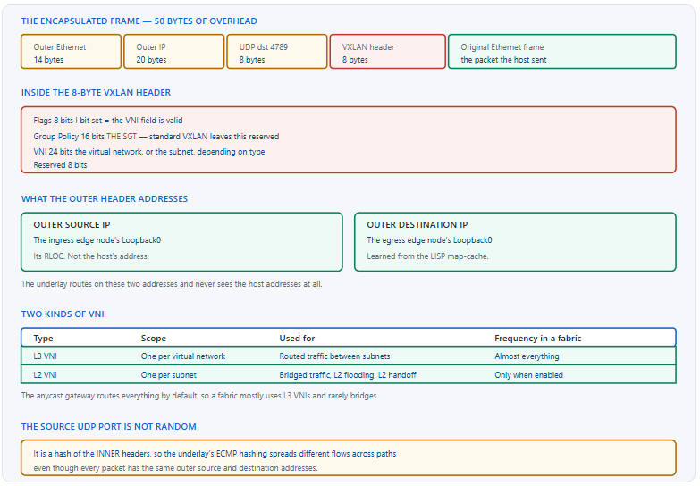
What Is Actually in a Fabric VXLAN Header?
What does the header carry?
Four things that matter. A flag indicating the network identifier is valid. A 16-bit group policy field carrying the source's scalable group tag, which standard VXLAN leaves reserved. A 24-bit network identifier naming either a virtual network or a subnet depending on which kind it is. And, in the outer headers wrapping it, the source and destination edge node loopbacks that the underlay actually routes on.
A Deeper Dive into the Header
The group policy field
Sixteen bits repurposed from reserved space, carrying the group tag assigned to the source endpoint. Because it travels with the packet, the destination edge node knows both the source group — from the header — and the destination group — from its own local assignment, and can therefore evaluate policy without querying anything. That is the entire reason enforcement happens at the destination, and it is why a fabric can apply policy between two endpoints that have never had any control-plane interaction with each other.
! The tag that goes into the header, on the ingress edge
EDGE1# show cts role-based sgt-map vrf CAMPUS all
Active IPv4-SGT Bindings Information
IP Address      SGT     Source
10.10.10.55     10      LOCAL
!
! And what the egress edge does with it on arrival
EDGE2# show cts role-based permissions from 10 to 20
IPv4 Role-based permissions from group 10:Employees to group 20:Printers:
        Printer_Access-10
        Deny IP-00
!
EDGE2# show cts role-based counters | include 10 *20
The overhead, item by item
| Component | Size | Contains |
|---|---|---|
| Outer Ethernet | 14 bytes | Next-hop MAC addresses in the underlay |
| Outer IPv4 | 20 bytes | Ingress and egress RLOCs |
| UDP | 8 bytes | Destination port 4789; source port is a flow hash |
| VXLAN header | 8 bytes | Flags, group policy ID, VNI |
| Total | 50 bytes | Why the underlay MTU must be raised |
The source port, which is doing real work
Every packet between two edge nodes has the same outer source and destination address, which would normally mean every flow takes the same underlay path and equal-cost links go unused. The source UDP port is computed from the inner headers instead of being fixed, so different inner flows produce different source ports and the underlay's hashing spreads them across available paths. This is why the underlay's load balancing works at all despite the outer addressing being identical.
! Confirm the underlay is actually spreading traffic
CORE1# show interfaces TenGigabitEthernet1/1/1 | include rate
  30 second input rate 2814000 bits/sec
  30 second output rate 3102000 bits/sec
CORE1# show interfaces TenGigabitEthernet1/1/2 | include rate
  30 second input rate 2790000 bits/sec
  30 second output rate 3044000 bits/sec
! ^ Two equal-cost links carrying similar load = hashing works.
!
! And the hashing configuration itself
CORE1# show etherchannel load-balance
CORE1# show ip cef exact-route 10.1.1.5 10.1.1.9
Why the encapsulation is UDP rather than something else
Wrapping the frame in UDP rather than in a bespoke protocol number is a pragmatic choice with two consequences that matter operationally. Every device in the path treats it as ordinary UDP, so firewalls, load balancers and hardware forwarding paths handle it without needing to understand VXLAN at all. And the source port field becomes available as a place to put entropy, which is what makes underlay load balancing work.
The cost is that the encapsulation is filterable by anything that filters UDP, which is occasionally the cause of a fabric that works within a building and fails between buildings — a firewall in the path permitting the control plane's port and not the data plane's. The two ports are different numbers and they get permitted separately, which is exactly the kind of rule that gets half-written.
What the underlay sees
Nothing about the endpoints. The outer header contains two loopback addresses, and every intermediate device forwards on those exactly as it would forward any other IP packet. That is why an intermediate node needs no fabric configuration, why the underlay routing table stays small regardless of endpoint count, and why an underlay packet capture shows no host addresses at all unless you decode past the encapsulation.
! What an intermediate node sees - just IP between loopbacks
CORE1# show ip route 10.1.1.9
Routing entry for 10.1.1.9/32
  Known via "isis", distance 115, metric 20
!
CORE1# show ip cef 10.1.1.9
10.1.1.9/32
  nexthop 10.100.0.5 TenGigabitEthernet1/1/3
!
! No fabric configuration on this device at all
CORE1# show run | include lisp|vxlan|cts
! ^ Empty. It is a router carrying IP.
What Happens to a Packet From Ingress to Egress?
What is the sequence?
The packet arrives on an access port and is associated with a subnet and a group tag. The edge node routes it, because the anycast gateway is local, and the route resolves through the mapping cache to a remote edge node's loopback. It is encapsulated with that loopback as the outer destination, the virtual network's identifier as the VNI, and the source's group tag in the policy field. The underlay carries it. The far edge node de-encapsulates, evaluates policy using the tag it received and the destination's own tag, and delivers or discards.
A Deeper Dive into the Path
The ingress decision
The critical thing to understand is that the edge node routes rather than bridges. The host sends the packet to its default gateway, which is the switch it is plugged into, and the switch performs a normal IP lookup in the virtual network's routing table. That lookup resolves to a virtual interface representing the fabric, and the mapping cache supplies the remote loopback. Everything about the fabric happens after an ordinary routing decision.
! The route lookup that starts everything
EDGE1# show ip route vrf CAMPUS 10.10.20.44
Routing entry for 10.10.20.0/24
  Known via "lisp", distance 250, metric 1
  Routing Descriptor Blocks:
  * 10.1.1.9, from 10.1.1.9
      Route metric is 1, traffic share count is 1
!
! And how CEF resolves it - through the LISP interface
EDGE1# show ip cef vrf CAMPUS 10.10.20.44
10.10.20.44/32
  nexthop 10.1.1.9 LISP0.4099
! ^ LISP0.4099 is the encapsulation interface for instance 4099.
!
! Which in turn resolves in the UNDERLAY table
EDGE1# show ip cef 10.1.1.9
Encapsulation and the two lookups
Two routing lookups happen for every fabric packet: one in the virtual network's table to find the remote edge node, and one in the underlay's table to find the path to that node's loopback. They are entirely independent — the first is overlay routing driven by the mapping system, the second is ordinary IGP routing. A great deal of fabric troubleshooting is establishing which of the two lookups is failing.
! Lookup one: overlay, in the VN's table
EDGE1# show ip route vrf CAMPUS 10.10.20.44
EDGE1# show lisp instance-id 4099 ipv4 map-cache 10.10.20.44
!
! Lookup two: underlay, in the global table
EDGE1# show ip route 10.1.1.9
EDGE1# ping 10.1.1.9 source Loopback0 size 9000 df-bit
!
! Both must succeed. Failing at one looks like failing at
! the other unless you check them separately.
The egress decision, where policy lives
The far edge node strips the encapsulation and now has the original packet plus two pieces of context: the source group from the header, and the destination group from its own local binding. It evaluates the policy matrix for that pair and either delivers the packet to the destination port or discards it. A discard here is silent from the source's perspective, which is why a policy denial presents as a connectivity problem rather than as an error.
! At the egress edge node - was policy the reason?
EDGE2# show cts role-based counters
Role-based IPv4 counters
From    To      SW-Denied  HW-Denied  SW-Permit  HW-Permit
10      20      0          4412       0          182004
! ^ A rising HW-Denied count between those groups is the answer.
!
! And the local binding that supplied the destination group
EDGE2# show cts role-based sgt-map vrf CAMPUS 10.10.20.44
EDGE2# show cts environment-data | include Server|status
Broadcast and multicast in the overlay
A fabric does not flood by default, because the control plane knows where every endpoint is and ARP is answered locally rather than broadcast. Where flooding is genuinely required — an enabled Layer 2 flooding subnet, or overlay multicast — there are two mechanisms. Head-end replication has the ingress node send one unicast copy per receiving node, needing nothing of the underlay. Native multicast sends one copy into an underlay multicast tree, needing PIM everywhere.
| Mechanism | Copies sent by ingress | Underlay requirement | Suits |
|---|---|---|---|
| Head-end replication | One per receiving edge node | None | Low-rate groups, small fabrics |
| Native multicast | One | PIM on every node in the path | Video, large fabrics |
ARP, which never leaves the switch
A host ARPing for another host in its own subnet would normally broadcast. In a fabric the edge node intercepts that request, resolves the address through the control plane, and answers locally. The broadcast never traverses the fabric at all, which is why a fabric subnet spanning fifty switches generates no more broadcast traffic than one spanning one — and why a silent host that has never been learned cannot be ARPed for successfully.
! The switch answers on behalf of the remote host
EDGE1# show ip arp vrf CAMPUS 10.10.10.71
Protocol  Address     Age (min)  Hardware Addr   Type   Interface
Internet  10.10.10.71     2      a0b4.0102.7171  ARPA   Vlan1021
!
! Resolved through the control plane, not by flooding
EDGE1# show lisp instance-id 4099 ipv4 map-cache 10.10.10.71
!
! Which is why an unlearned host cannot be reached by ARP
EDGE1# show device-tracking database address 10.10.10.99
! ^ absent = nothing to answer with = unreachable
show lisp ... map-cache and a full-MTU loopback ping as two distinct checks takes twenty seconds and eliminates the possibility of investigating the wrong one.How Do L2 and L3 VNIs Differ, and When Is Each Used?
What is the distinction?
An L3 VNI identifies a virtual network and is used when the fabric routes, which is nearly always. An L2 VNI identifies a specific subnet and is used when the fabric bridges — Layer 2 flooding for silent hosts, a Layer 2 handoff at the border, or extending a subnet to something outside the fabric. A default fabric with no flooding enabled uses L3 VNIs for essentially all traffic, and encountering an L2 VNI means some Layer 2 behaviour has been deliberately turned on.
A Deeper Dive into the Two Types
Why routing is the default
The anycast gateway means every host's default gateway is the switch it is attached to, so traffic to any other subnet is routed immediately at the first hop. Traffic within the same subnet but to a different switch is also routed, because the fabric resolves the destination through the control plane and forwards to the remote edge node rather than bridging a frame across. The subnet exists as an addressing construct rather than as a broadcast domain, which is the property that lets it span the entire fabric without cost.
! Same subnet, different switches - and it is still routed
EDGE1# show ip route vrf CAMPUS 10.10.10.71
Routing entry for 10.10.10.71/32
  Known via "lisp", distance 250, metric 1
  * 10.1.1.9, from 10.1.1.9
! ^ A HOST route to a peer in the same subnet, via the fabric.
!
! The L3 VNI in use for the VN
EDGE1# show lisp instance-id 4099 ipv4 | include EID-table
  EID-table:  vrf CAMPUS
EDGE1# show run | include instance-id 4099
When an L2 VNI appears
Three circumstances. Layer 2 flooding enabled on a subnet, usually to accommodate devices that need broadcast to be discovered. A Layer 2 handoff at the border, extending a fabric subnet out as an ordinary VLAN for migration or for an appliance that requires adjacency. And Layer 2 border designs generally, which are migration constructs rather than steady-state ones.
! Layer 2 flooding on a subnet - reintroduces broadcast
! Configured from the controller; requires underlay multicast
!
EDGE1# show run interface Vlan1021 | include flood|lisp
 lisp mobility 10_10_10_0-CAMPUS-IPV4
!
! The L2 instance that carries the flooded traffic
EDGE1# show lisp instance-id 8188 ethernet database
EDGE1# show lisp instance-id 8188 ethernet map-cache
! ^ Note "ethernet" rather than "ipv4" - that is an L2 VNI.
!
! And the underlay multicast it depends on
EDGE1# show ip pim interface
EDGE1# show ip mroute count
The cost of turning flooding on
Layer 2 flooding puts broadcast traffic back into a subnet that may span the whole fabric, and it requires native multicast in the underlay to do so efficiently. Both are real costs. The correct approach is to enable it for the specific subnet containing the devices that need it rather than broadly, and to identify those devices during discovery rather than by enabling flooding to make an unexplained problem disappear.
The two side by side
| Property | L3 VNI | L2 VNI |
|---|---|---|
| Scope | One virtual network | One subnet |
| Inner frame | Routed — MAC rewritten | Bridged — original MACs preserved |
| Used by default | Yes, for nearly all traffic | No |
| Requires underlay multicast | No | For flooding, yes |
| Typical trigger | Any inter-host traffic | L2 flooding, L2 handoff, migration |
| Verification command family | ... ipv4 map-cache |
... ethernet map-cache |
show ip pim interface on intermediate nodes is empty; show ip mroute shows no state for the fabric's flooding groups. Fix: configure PIM on every underlay interface in the path, including on intermediate nodes that otherwise carry no fabric configuration.How Does the Hardware Actually Forward This?
Is any of this in software?
No, on the platforms a fabric is built from. Encapsulation, de-encapsulation, the VNI lookup and the policy evaluation all happen in the forwarding ASIC at line rate. That matters because it means a fabric edge node's CPU load says nothing about how much traffic it is forwarding, and it means a rising CPU is a signal that something is being punted to software — which is a fault rather than a load characteristic.
A Deeper Dive into Hardware Forwarding
What being punted to software looks like
A packet that cannot be handled by the ASIC is sent to the CPU, which handles it far more slowly and at a rate limit. Small numbers of punted packets are normal — control traffic, the first packet of a conversation while a lookup completes. A sustained rate is not, and it produces the combination of high CPU, packet loss under load, and normal-looking configuration that is characteristic of a hardware resource problem.
! Is the CPU doing work it should not be?
EDGE1# show processes cpu sorted | exclude 0.00
CPU utilization for five seconds: 71%/38%; one minute: 68%
! ^ The second number is interrupt-level. High = punting.
!
! What is being punted, and why
EDGE1# show platform software fed switch active punt cause summary
EDGE1# show platform software fed switch active punt cpuq brief
!
! And whether anything is being dropped on the way
EDGE1# show platform software fed switch active punt cpuq 0 | include drop
Table capacity, which is finite
The forwarding tables that hold mapping entries, policy bindings and the tag matrix are hardware resources with fixed sizes. Exhausting any of them produces behaviour that is correct for most traffic and wrong for some, with no obvious pattern to which — because which entries got in depends on the order they arrived. Checking utilisation is a routine health item and it is almost never done until something is already wrong.
! Hardware resource utilisation
EDGE1# show platform hardware fed switch active fwd-asic resource tcam utilization
!
! Policy-specific table usage
EDGE1# show cts role-based counters
EDGE1# show platform software fed switch active cts_sgacl summary
!
! And the endpoint-related tables
EDGE1# show device-tracking database | count REACHABLE
EDGE1# show lisp instance-id 4099 ipv4 map-cache | include entries
Where the tag comes from at line rate
The ingress ASIC needs the source's group tag for every packet it encapsulates, which means the tag has to be in a hardware table indexed by source address. That table is populated when the endpoint authenticates or when a static binding is configured, and a packet from an address with no binding gets the default tag rather than no tag. An unexpected default tag on traffic is therefore a binding problem rather than a policy problem, and the two are diagnosed in different places.
! Is the binding actually in hardware?
EDGE1# show cts role-based sgt-map vrf CAMPUS 10.10.10.55
IP Address    SGT   Source
10.10.10.55   10    LOCAL
!
! An address with no binding gets the default
EDGE1# show cts role-based sgt-map vrf CAMPUS 10.10.10.99
! ^ absent = default tag applied = policy will not match
!   the rule you expected
!
! What the default is
EDGE1# show cts role-based permissions default
QoS across the encapsulation
The original packet's marking is inside the encapsulation where the underlay cannot see it, so the encapsulating node copies the inner marking into the outer header. That is what allows intermediate nodes to apply queueing correctly without decoding anything. It also means a re-marking policy applied in the underlay affects the outer header only, and the inner marking survives to the far edge unchanged — which is usually the desired behaviour and occasionally a surprise.
The practical implication is that a QoS problem in a fabric is diagnosed in two places, exactly like a routing problem. The inner marking is what the destination sees and is set at the ingress edge; the outer marking is what the underlay acts on and is derived from it. Checking both is the difference between finding the problem and concluding that QoS is not working.
! What the ingress edge marks, on the access side
EDGE1# show policy-map interface GigabitEthernet1/0/12 input
!
! And what the underlay is queueing on
CORE1# show policy-map interface TenGigabitEthernet1/1/1 output
CORE1# show platform hardware fed switch active qos queue stats interface Te1/1/1
!
! Confirm the outer marking reflects the inner one
EDGE1# show mls qos interface GigabitEthernet1/0/12 statistics
Capturing fabric traffic
An embedded capture on an underlay link shows encapsulated packets, and decoding them requires the capture tool to understand the encapsulation. Filtering on the outer addresses — two loopbacks — narrows to traffic between a specific pair of edge nodes, which is usually the right scope. Capturing on the access port instead shows the original frame with no encapsulation, which answers a different and often more useful question.
! Capture on the underlay - encapsulated traffic
ip access-list extended FABRIC-CAP
 permit ip host 10.1.1.5 host 10.1.1.9
 permit ip host 10.1.1.9 host 10.1.1.5
!
monitor capture CAP interface TenGigabitEthernet1/1/1 both
monitor capture CAP access-list FABRIC-CAP
monitor capture CAP buffer size 10
monitor capture CAP start
!
EDGE1# show monitor capture CAP buffer brief
EDGE1# monitor capture CAP stop
EDGE1# monitor capture CAP export flash:fabric.pcap
!
! Or capture the original frame on the access port instead
monitor capture ACC interface GigabitEthernet1/0/12 both
Which Data Plane Failures Are Not Control Plane Failures?
What are the failures worth memorising?
Four. MTU, which is the dominant one and produces size-dependent failure. An underlay path that is broken or asymmetric, which the fabric inherits directly. A policy denial at the egress node, which is a deliberate discard presenting as a connectivity problem. And a hardware table that has filled, which produces correct behaviour for most traffic and silent failure for the rest.
A Deeper Dive into the Failure Catalogue
Size-dependent failure
ping <remote-loopback> source Loopback0 size 9000 df-bit fails while a smaller size succeeds; bisecting the size locates the exact limit. Fix: raise the MTU to 9100 on every link in the path, including devices the controller does not manage — which is where the shortfall almost always is.The policy discard
show cts role-based counters on the egress node shows a rising denied count for that group pair. Fix: correct the policy, or correct the group assignment — and note that the diagnosis has to happen on the destination switch, which is not where the investigation usually starts.The filled table
A four-step data plane check
! In this order, and stop at the first failure
!
! 1. Underlay, at full MTU
EDGE1# ping 10.1.1.9 source Loopback0 size 9000 df-bit
!
! 2. Overlay resolution
EDGE1# show ip cef vrf CAMPUS 10.10.20.44
! ^ must resolve via LISP0.<instance-id>
!
! 3. Policy at the EGRESS node, not the ingress
EDGE2# show cts role-based counters | include Denied
!
! 4. Hardware health on both
EDGE1# show platform software fed switch active punt cause summary
EDGE1# show processes cpu sorted | include Interrupt|five seconds
What to monitor
Four items that no fabric dashboard covers by default and that between them catch every failure in this article. Loopback-to-loopback reachability at full MTU, run periodically rather than once. Punt rate per edge node, alerting on a sustained increase. Hardware table utilisation, alerting well before capacity. And policy denial counters, which distinguish an intended denial from a misconfiguration only if you have a baseline to compare against.
Why the shape of a failure is the diagnosis
Data-plane failures in a fabric come in a small number of shapes and each shape maps to one cause. Failure that depends on packet size is MTU and nothing else. Failure that depends on which two groups are talking is policy. Failure that depends on which pair of edge nodes is involved is the underlay path between them. Failure affecting an apparently arbitrary subset, with elevated CPU, is a hardware table.
Establishing the shape before running any command is worth the thirty seconds it takes, because it turns a broad investigation into a single confirmation. The question to ask the person reporting it is not "what is broken" but "what still works" — the boundary between the two is what identifies the shape, and it is information they already have.
Blueprint framing
The CCIE Enterprise Infrastructure v1.1 blueprint covers the SD-Access data plane within the software-defined infrastructure domain, and the questions concentrate on the encapsulation: what VXLAN carries, why the MTU requirement exists, what the group policy field is for, and where enforcement happens. Being able to state the 50-byte overhead and explain destination enforcement covers most of what is asked.
Keeping a known-good baseline
Most of the commands in this article are only useful relative to what they showed when the fabric was working. A punt rate means nothing without knowing the normal one; a policy denial counter means nothing without knowing which denials are intended. Capturing that baseline once, shortly after commissioning and before the fabric carries anything important, converts a whole family of ambiguous outputs into unambiguous ones.
The set worth capturing is small: punt cause summary and CPU on a representative edge node, hardware table utilisation on the same, policy counters per group pair, and the full-mesh MTU test result. Stored with a date, that becomes the reference every subsequent investigation compares against, and it costs one afternoon at the only point in the project when nothing is on fire.
Conclusion
The fabric data plane is VXLAN with the reserved bits put to work. Twenty-four of them name the virtual network, sixteen carry the source's group tag, and that second field is what makes destination enforcement possible — the receiving switch knows both groups without asking anything. Every other property follows: the 50-byte overhead that makes MTU a design input, the outer addressing that keeps the underlay ignorant of endpoints, and the source port that is a flow hash so equal-cost paths get used.
Two routing lookups happen for every packet, in two independent tables, and separating them is most of what data-plane troubleshooting consists of. The overlay lookup resolves the destination to a remote edge node through the mapping cache; the underlay lookup finds the path to that node's loopback. They fail differently, they are fixed differently, and they produce the same symptom, which is why running both checks explicitly beats reasoning about which is more likely.
The failures worth memorising have shapes that identify them. Size-dependent failure is MTU, every time. Failure between specific group pairs is policy, checked at the destination rather than the source. Failure affecting an arbitrary subset with elevated CPU is a hardware table at capacity. And a fabric edge node's CPU should be idle regardless of throughput, which makes a busy one a fault report rather than a capacity observation.
External Links
- RFC 7348 — Virtual eXtensible Local Area Network (VXLAN)
- RFC 9300 — The Locator/ID Separation Protocol (LISP)
- RFC 8014 — An Architecture for Data-Center Network Virtualization over Layer 3
- Cisco TrustSec Configuration Guide
- Cisco — Software-Defined Access Configuration Guide, Catalyst 9300
- Cisco Design Zone — Campus Wired and Wireless Design Guides
- Cisco Learning Network — CCIE Enterprise Infrastructure
Reference Notes
- RFC 7348 defines VXLAN, specifying an 8-byte VXLAN header containing a flags field, a 24-bit VXLAN Network Identifier, and reserved fields.
- RFC 7348 assigns UDP destination port 4789 to VXLAN and recommends deriving the source port from the inner packet headers so that equal-cost paths in the underlay can be used.
- RFC 7348 notes that VXLAN encapsulation adds 50 bytes to the original frame on an IPv4 underlay, requiring the underlying network to support a correspondingly larger MTU.
- Cisco documentation describes the Group Policy Option extension to the VXLAN header, which uses reserved bits to carry a 16-bit group policy identifier.
- Cisco TrustSec documentation describes enforcement at the destination, using the source group tag carried with the packet and the destination endpoint's locally known group.
- Cisco documentation describes the L3 VNI as corresponding to a virtual network and the L2 VNI as corresponding to a subnet used for bridged forwarding.
- Cisco documentation describes the anycast gateway, which causes a fabric edge node to route traffic from directly attached hosts rather than bridging it.
- Cisco documentation describes head-end replication and native multicast as the two mechanisms for delivering broadcast, unknown unicast and multicast traffic in a fabric overlay.
- Cisco documentation describes Layer 2 flooding as an optional per-subnet capability requiring underlay multicast support.
- RFC 9300 defines the routing locator, which in SD-Access is the fabric node loopback used as the outer source and destination address of the encapsulated packet.
- Cisco documentation describes the LISP virtual interface used as the CEF adjacency for fabric-encapsulated traffic, named for the instance ID it serves.
- The CCIE Enterprise Infrastructure v1.1 unified exam topics include the SD-Access data plane within the software-defined infrastructure domain.