

The underlay is the part of SD-Access that gets the least attention and causes the most outages. It has no virtual networks, no group tags, no LISP and no VXLAN — it is a plain routed IP network whose entire job is to carry packets between fabric node loopbacks. That simplicity is why it is skipped in design reviews, and it is also why an underlay with one MTU exception or one asymmetric path produces fabric symptoms that look like anything except the underlay.
LAN Automation exists to remove the manual work and, more importantly, to remove the inconsistency. A human building forty switches by hand will get thirty-nine of them right, and the fortieth will have a 1500-byte MTU on one uplink or a loopback that was never advertised. The automation produces identical configuration on every device because it generates rather than types it, and the value of that is less about time saved than about the class of error it eliminates entirely.
This article covers what the underlay must actually provide, how to build it manually when that is the right choice, what LAN Automation does and what it requires, how to prepare a site so the automation succeeds on the first attempt, and the failure catalogue — the underlay problems that present as fabric problems and get diagnosed in the wrong plane.
What Does an SD-Access Underlay Actually Have to Provide?
What is the requirement list?
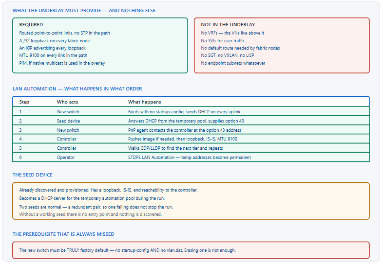
Five things. Routed point-to-point links between fabric nodes, so that no spanning tree topology exists in the path. A /32 loopback on every fabric node, which is the routing locator that VXLAN tunnels are built between. An IGP that advertises every one of those loopbacks to every other node. An MTU of 9100 on every link in the path, including devices the controller does not manage. And PIM, if and only if the overlay will use native multicast rather than head-end replication.
A Deeper Dive into the Requirements
Routed links, and why Layer 2 in the path is a problem
A fabric between two edge nodes is a VXLAN tunnel between two loopbacks, and the underlay's job is to deliver those packets by the shortest available path with fast reconvergence. A Layer 2 segment anywhere in that path introduces spanning tree, which converges more slowly than any IGP, blocks links that the underlay would otherwise use, and adds a failure mode the fabric has no visibility into. Point-to-point routed links remove all three.
! What an underlay link looks like - nothing fabric-specific
interface TenGigabitEthernet1/1/1
 description UNDERLAY to CORE-1
 no switchport
 ip address 10.100.0.1 255.255.255.254
 ! ^ a /31. Two usable addresses, no waste.
 ip mtu 9100
 ip router isis
 isis network point-to-point
 bfd interval 250 min_rx 250 multiplier 3
 load-interval 30
!
! And the loopback that everything is built on
interface Loopback0
 description RLOC
 ip address 10.1.1.5 255.255.255.255
 ip router isis
MTU, which is not negotiable
VXLAN adds 50 bytes to every frame. A 1500-byte underlay carries small packets and silently discards full-size ones somewhere in the middle of the fabric, which produces the characteristic symptom of a network where ping works and applications do not. 9100 is the recommended value, it must be set on every link in the path, and the devices most likely to be missed are the ones the controller does not manage — a transit switch, a service provider handoff, a firewall in the path between sites.
! The definitive test, run between every pair of fabric loopbacks
EDGE1# ping 10.1.1.9 source Loopback0 size 9000 df-bit
Type escape sequence to abort.
Packet sent with the DF bit set
!!!!!
Success rate is 100 percent (5/5), round-trip min/avg/max = 1/1/2 ms
!
! A failure here locates the problem before any endpoint exists
EDGE1# ping 10.1.1.9 source Loopback0 size 9000 df-bit
.....
Success rate is 0 percent (0/5)
!
! Then bisect to find the link
EDGE1# ping 10.1.1.9 source Loopback0 size 1500 df-bit
EDGE1# traceroute 10.1.1.9 source Loopback0
The IGP, and why IS-IS is the automated choice
Any IGP works for a manually built underlay. LAN Automation provisions IS-IS, and the reason is structural: IS-IS runs directly over the data link layer rather than over IP, so an adjacency can form before addressing is settled. For an automation process that is provisioning addresses as it goes, a protocol that does not depend on those addresses being correct first is a considerable simplification.
! What LAN Automation provisions - level-2 only, one area
router isis
 net 49.0000.0100.0101.0005.00
 ! ^ area 49.0000, system ID derived from the loopback
 is-type level-2-only
 metric-style wide
 log-adjacency-changes
 nsf ietf
 bfd all-interfaces
!
! Verify the adjacencies
EDGE1# show isis neighbors
System Id      Type Interface     IP Address      State Holdtime Circuit Id
CORE-1         L2   Te1/1/1       10.100.0.0      UP    28       00
CORE-2         L2   Te1/1/2       10.100.0.2      UP    27       00
!
EDGE1# show isis database level-2 | include LSP|0100.0101
EDGE1# show clns interface TenGigabitEthernet1/1/1 | include Level-2
Convergence, which is the underlay's other job
The fabric inherits the underlay's convergence time exactly. A VXLAN tunnel between two loopbacks is unavailable for as long as the underlay takes to find a new path, and no amount of fabric configuration improves that. BFD on every underlay link, with tuned IGP timers, is the mechanism — and it is worth configuring even in an automated underlay where it may not be provisioned by default.
| Underlay property | Recommended | Effect if wrong |
|---|---|---|
| Link type | Routed point-to-point | Spanning tree in the fabric path, slow convergence |
| Link addressing | /31 | Address waste only — not functional |
| MTU | 9100 | Silent discard of full-size frames |
| Loopback | /32 on every node, in the IGP | Tunnels cannot be built to that node |
| IGP | IS-IS (automated) or any (manual) | — |
| Failure detection | BFD, 250 ms | Fabric convergence inherits IGP hold timers |
| Multicast | PIM if native overlay multicast | Head-end replication only, which limits scale |
How Do I Build the Underlay Manually?
When is manual the right choice?
When the devices already exist and are carrying production traffic, because LAN Automation requires factory-default devices. When the underlay must use a specific IGP for organisational reasons. When the topology includes equipment the controller does not manage. And when the site is small enough that automating four switches costs more preparation than configuring them. Manual and automated underlays are equally supported; the automation is about consistency at scale rather than about capability.
A Deeper Dive into the Manual Build
A template, applied identically everywhere
The value of automation is consistency, and a manual build gets most of that by writing the configuration once as a template and generating per-device versions rather than typing each one. The parts that vary are the loopback address, the system ID and the link addresses; everything else should be byte-identical across the site, and a diff between two switches should show only those three categories of difference.
! ===== Underlay template - vary only the marked values =====
!
interface Loopback0
 description RLOC
 ip address <LOOPBACK> 255.255.255.255
 ip router isis
!
interface <UPLINK>
 description UNDERLAY to <NEIGHBOR>
 no switchport
 ip address <P2P> 255.255.255.254
 ip mtu 9100
 ip router isis
 isis network point-to-point
 bfd interval 250 min_rx 250 multiplier 3
 no shutdown
!
router isis
 net 49.0000.<SYSTEM-ID>.00
 is-type level-2-only
 metric-style wide
 log-adjacency-changes
 bfd all-interfaces
 passive-interface Loopback0
!
! Global, identical on every device
ip routing
ip cef
no ip domain lookup
system mtu 9198
Deriving a system ID that means something
The IS-IS system ID is six bytes and any unique value works, which makes it worth choosing a convention rather than accepting a random one. Deriving it from the loopback address — 10.1.1.5 becoming 0100.0100.1005 by zero-padding each octet — means the system ID in an adjacency table or an LSP identifies the device without a lookup, which is a small convenience that pays off during every incident.
! Loopback 10.1.1.5  ->  zero-pad each octet to three digits
!   010.001.001.005  ->  regroup into three 2-byte fields
!   0100.0100.1005
!
router isis
 net 49.0000.0100.0100.1005.00
!
! Now the adjacency table is self-documenting
CORE1# show isis neighbors
System Id      Type Interface  IP Address    State Holdtime
0100.0100.1005 L2   Te1/1/1    10.100.0.1    UP    29
! ^ That is 10.1.1.5, readable without a lookup.
Multicast in the underlay
Native overlay multicast requires the underlay to forward multicast between fabric nodes, which means PIM on every underlay interface including on intermediate nodes that otherwise need no fabric configuration. SSM is the usual choice because it needs no rendezvous point and therefore no RP redundancy design, and because the fabric's use of multicast is inherently source-specific.
! Underlay multicast, on every node in the path
ip multicast-routing
ip pim ssm default
! ^ SSM in 232.0.0.0/8. No RP needed at all.
!
interface Loopback0
 ip pim sparse-mode
interface TenGigabitEthernet1/1/1
 ip pim sparse-mode
!
! Verify on every hop, including intermediate nodes
CORE1# show ip pim interface
CORE1# show ip pim neighbor
CORE1# show ip mroute count
Why the underlay should be deliberately boring
There is a temptation to make the underlay do more than carry loopback traffic — to summarise it, to filter it, to add a default route, to run it in a VRF for tidiness. Every one of those additions creates a way for the fabric to break that has no fabric-visible symptom, and none of them buys anything, because the underlay routing table on even a large campus is a few dozen /32s and a set of link prefixes that never change.
Summarisation is the most common of these and the most damaging. Summarising loopbacks at a distribution boundary means a node whose loopback disappears is still covered by the summary, so the IGP continues to advertise reachability to an address that no longer answers, and VXLAN tunnels to it fail without any routing change to point at. The underlay is small enough that carrying every /32 individually costs nothing and preserves exactly the failure signal that summarisation removes.
Verification before handing the underlay to the fabric
! Full-mesh loopback reachability at full MTU
! Run from every node to every other node
!
for each remote loopback:
  ping <remote> source Loopback0 size 9000 df-bit
!
! Then confirm the IGP sees every loopback
EDGE1# show ip route isis | count /32
Number of lines which match regexp = 14
! ^ Should equal (number of fabric nodes - 1).
!
! And that BFD is actually up, not just configured
EDGE1# show bfd neighbors
IPv4 Sessions
NeighAddr        LD/RD    RH/RS   State  Int
10.100.0.0       1/1      Up      Up     Te1/1/1
10.100.0.2       2/1      Up      Up     Te1/1/2
What Does LAN Automation Actually Do?
What is the process?
A seed device that is already provisioned becomes a temporary DHCP server. New switches boot with no configuration, request an address, receive one from a temporary pool along with an option pointing at the controller, and their Plug and Play agent contacts it. The controller upgrades the software if needed, then provisions a loopback, IS-IS, MTU and management configuration. It then reads the new device's neighbour tables to find the next tier and repeats, walking outward from the seed until the topology is complete.
A Deeper Dive into LAN Automation
The seed device, and why there are two
The seed is the entry point: it must already be discovered by the controller, must have a loopback and IS-IS, and must be reachable. During the run it hosts the DHCP scope for the temporary pool. Two seeds are the normal configuration, because a run that depends on a single device stops entirely if that device has a problem partway through — and a partially completed run leaves devices in a state that has to be cleaned up manually.
! What the seed looks like before a run - already provisioned
SEED1# show run | include ^router isis|^ip routing|net 49
ip routing
router isis
 net 49.0000.0100.0100.1001.00
!
SEED1# show ip interface brief | include Loopback0
Loopback0    10.1.1.1   YES manual up   up
!
! And what appears on it during the run
SEED1# show ip dhcp pool
Pool LAN_AUTOMATION_POOL :
 Utilization mark (high/low)    : 100 / 0
 Subnet size (first/next)       : 0 / 0
 Total addresses                : 254
 Leased addresses               : 7
! ^ Seven devices have picked up temporary addresses.
Factory default, which means more than erasing the config
A switch is ready for Plug and Play only if it has no startup configuration and no VLAN database. Erasing the startup config alone leaves vlan.dat in place, the switch boots with residual VLAN state, and the PnP agent does not start. This is the single most common reason a LAN Automation run finds fewer devices than expected, and it is entirely silent — the device simply never appears in the discovery list.
! Both of these, then reload. One is not enough.
SW# write erase
Erasing the nvram filesystem will remove all configuration files!
Continue? [confirm]
!
SW# delete /force flash:vlan.dat
!
! On a stack, also clear the stack config if repurposing
SW# delete /force flash:*.bin.old
!
SW# reload
System configuration has been modified. Save? [yes/no]: no
!
! Confirm PnP started after the reload
SW# show pnp summary
SW# show pnp profile
SW# show pnp tech-support | include state|server
What the automation actually configures
| Element | Provisioned as | Worth verifying after |
|---|---|---|
| Loopback0 | /32 from the pool you specified | Present in the IGP on every other node |
| Point-to-point links | /31, routed, MTU 9100 | MTU on links to unmanaged devices |
| IGP | IS-IS level-2-only | Adjacency count matches the topology |
| Management | SSH, AAA, NTP, SNMP | Reachable from the controller after the run |
| Software version | Upgraded to the golden image if needed | Consistent across the site |
| BFD | Varies by release | Add it if absent |
Stopping the run, which is a required step
LAN Automation is not finished when the devices appear. Stopping the run converts the temporary DHCP-assigned addressing into the permanent loopback-based configuration, removes the temporary pool from the seed, and releases the seed from its DHCP server role. A run left running holds resources and leaves devices on temporary addressing, which works until the leases expire.
! After stopping, confirm the temporary pool is gone
SEED1# show ip dhcp pool
! ^ Should be empty. If the LAN_AUTOMATION_POOL is still
!   present, the run was never stopped.
!
! And that the new devices are on permanent addressing
NEW-SW# show ip interface brief | include Loopback0
Loopback0    10.1.1.12   YES manual up   up
!
NEW-SW# show isis neighbors
NEW-SW# show run | include ^ip dhcp|^interface Vlan1$
! ^ No leftover DHCP client configuration.
Discovery topology and its limits
The controller walks outward using neighbour discovery, which means every device to be automated must be reachable through a chain of already-automated devices back to the seed. A switch connected only through a device that is not part of the run, or through a link that is down at the time, is not discovered — and the failure is silent, appearing as a device that simply is not in the list. Checking the neighbour tables before starting a run predicts exactly which devices will be found.
! Predict the discovery before running it
SEED1# show cdp neighbors
Device ID    Local Intrfce  Holdtme  Capability  Platform  Port ID
SW-A         Ten 1/1/1      154      S I         C9300     Ten 1/1/1
SW-B         Ten 1/1/2      171      S I         C9300     Ten 1/1/1
! ^ These two will be found in the first tier.
!
! CDP must be enabled - it is by default, and gets disabled
SEED1# show cdp | include enabled|not enabled
Global CDP information:
        Sending CDP packets every 60 seconds
!
SEED1# show lldp neighbors
show pnp profile on the device names an unexpected server. Fix: a full write erase plus delete /force flash:vlan.dat plus reload; if the profile persists, remove it explicitly with no pnp profile before erasing.How Do I Prepare a Site So LAN Automation Succeeds?
What has to be true before starting?
Six things, and every one of them fails silently if it is not. The seed is provisioned and reachable. The new devices are genuinely factory default. Their software version is supported and, ideally, already the golden image. The cabling matches the intended topology and every link is up. Address pools for the loopbacks and the temporary DHCP scope are defined and large enough. And the physical uplinks are the ones the controller expects, because a device cabled through an unmanaged switch is not discoverable.
A Deeper Dive into Preparation
A pre-flight checklist worth running
! ===== On the seed devices =====
show ip interface brief | include Loopback0
! ^ loopback present and up
show isis neighbors
! ^ IS-IS already running
ping <controller-ip> source Loopback0
! ^ controller reachable from the seed
show cdp neighbors
! ^ every device you expect to discover is listed
show ip dhcp pool
! ^ no leftover pool from a previous run
!
! ===== On each new device, via console =====
show version | include Version|System image
! ^ supported release, ideally the golden image already
dir flash: | include vlan.dat
! ^ MUST be absent
show pnp summary
! ^ PnP agent running, no stale server address
show interfaces status | include connected
! ^ the intended uplinks are actually up
Address pool sizing
Two pools are needed and both are easy to under-size. The loopback pool must hold one /32 per device with room for growth, since adding devices later draws from the same pool. The temporary DHCP pool must hold one address per device being discovered simultaneously, plus the point-to-point link addressing the automation allocates. Running out mid-run leaves the site partially provisioned, which is the most awkward possible state to recover from.
The six prerequisites and how each one fails
| Prerequisite | Check with | Symptom if missing |
|---|---|---|
| Seed provisioned and reachable | ping <controller> source Lo0 |
Run does not start, or starts and finds nothing |
| Device truly factory default | dir flash: \| include vlan.dat |
Device never appears in the discovery list |
| Supported software version | show version |
Discovery succeeds, provisioning fails partway |
| Cabling matches the topology | show cdp neighbors on the seed |
A tier is silently skipped |
| Pools large enough | Controller pool definition | Run stops mid-way, partial state |
| No stale PnP profile | show pnp profile |
Device contacts the wrong controller forever |
Recovering a partially completed run
A run that stops halfway leaves some devices provisioned, some on temporary addressing, and some untouched. The recovery is mechanical rather than clever: stop the run properly, identify which devices reached which state, return the incomplete ones to factory default, fix whatever caused the stop, and run again. Attempting to hand-finish a partially automated device produces configuration that differs from its peers, which is precisely what the automation existed to prevent.
! Triage - which state is each device in?
!  A. Fully provisioned: loopback + IS-IS + MTU, in the controller
!  B. Temporary only: DHCP address, no loopback, PnP contacted
!  C. Untouched: still factory default
!
SW# show ip interface brief | include Loopback0
SW# show isis neighbors
SW# show pnp summary
!
! State B devices go back to C before retrying
SW# write erase
SW# delete /force flash:vlan.dat
SW# reload
! ^ Do NOT hand-finish a state B device. Reset and re-run.
What to verify after a successful run
The automation reports success when it has provisioned the devices it found. That is not the same as the underlay being correct, and three checks close the gap: the full-mesh MTU test at 9000 bytes, the loopback count in the IGP matching the device count, and BFD sessions actually being up on every link rather than merely configured. All three are quick and all three catch things the automation cannot see — particularly MTU on links to devices it does not manage.
! Post-run verification - three checks, in this order
!
! 1. Every loopback is in the IGP on every node
EDGE1# show ip route isis | count /32
!
! 2. Full MTU between every pair of loopbacks
EDGE1# ping 10.1.1.9 source Loopback0 size 9000 df-bit
!
! 3. BFD sessions up, not just configured
EDGE1# show bfd neighbors | count Up
!
! And confirm consistency across devices
EDGE1# show run | include ^ip mtu|^system mtu
EDGE2# show run | include ^ip mtu|^system mtu
! ^ These should be identical. Any difference is a finding.
Extending the fabric later
Adding a switch to an existing fabric uses the same mechanism: put it in factory default, cable it to an already-provisioned device, and run LAN Automation again with that device as the seed. This is why the loopback pool should be sized generously at the start — the alternative is a second pool with a different summary, which complicates the IGP and the documentation for no benefit.
Which Underlay Problems Present as Fabric Problems?
What are the failures worth memorising?
Five. The MTU exception on an unmanaged link. A loopback that is not advertised, so tunnels to that node cannot be built. An asymmetric underlay path, which is harmless for the underlay and problematic for anything doing reverse-path checks above it. An IGP that converges slowly, which the fabric inherits exactly. And underlay multicast that is absent when the overlay expects native replication.
A Deeper Dive into the Failure Catalogue
The unmanaged link
ping <remote-loopback> source Loopback0 size 9000 df-bit fails while the same test at 1400 succeeds; bisecting locates the link. Fix: raise the MTU on the intervening device, or where that is impossible, accept the reduced MTU and configure the fabric accordingly — but know that this is a constraint rather than a default.The missing loopback
ip router isis on Loopback0, or a passive-interface configuration that excluded it. VXLAN tunnels are built loopback to loopback, so an unreachable loopback means no tunnel can be established to that node. Confirm: show ip route 10.1.1.x from another fabric node returns nothing; show ip route isis \| count /32 is one short. Fix: add the loopback to the IGP, and add the loopback count check to the post-provisioning verification so it is caught before endpoints are onboarded.Slow convergence inherited
show bfd neighbors is empty; show isis neighbors shows default holdtimes. Fix: BFD on every underlay link with a 250 ms interval, and bfd all-interfaces under the IS-IS process so that the IGP reacts to BFD rather than to its own timers.Telling underlay from overlay quickly
Three commands separate the two conclusively. If loopback-to-loopback ping at full MTU fails, it is the underlay and nothing above it can work. If that succeeds and the LISP map-cache is empty, it is the control plane. If both are fine and traffic still fails, it is policy or the data plane at the edge. Running them in that order means never investigating the overlay while the underlay is broken, which is the most common wasted hour in fabric troubleshooting.
! Underlay or overlay? Three commands.
!
! 1. Underlay - full MTU, loopback to loopback
EDGE1# ping 10.1.1.9 source Loopback0 size 9000 df-bit
! ^ fails = underlay. Stop here. Nothing above it can work.
!
! 2. Control plane - is the remote endpoint known?
EDGE1# show lisp instance-id 4099 ipv4 map-cache 10.10.10.71
! ^ empty = control plane. The host was never registered.
!
! 3. Policy - is anything denying it?
EDGE2# show cts role-based permissions
EDGE2# show cts role-based counters | include Deny
Monitoring the underlay separately
Because the underlay has no fabric-specific telemetry, it needs its own monitoring: IS-IS adjacency state per link, BFD session state, loopback reachability between every pair of nodes, and interface MTU as a configuration compliance check rather than a metric. These are ordinary network monitoring items and they are frequently omitted, because the fabric dashboard is green and appears to cover everything.
Change control for a layer nobody thinks about
The underlay is stable enough that months pass without anyone touching it, which means the person making a change to it is rarely the person who built it and rarely aware that it is load-bearing for the entire fabric. A transceiver swap that reduces MTU, a link re-patched through a media converter, a switch replaced under warranty with a default configuration — each is a routine action with a fabric-wide consequence.
The practical protection is documentation at the point of change rather than in a design document nobody opens. An interface description reading UNDERLAY - SD-Access fabric - MTU 9100 REQUIRED is read by whoever is about to change that interface, which a design document is not. Combined with a scheduled full-mesh MTU test, it converts this category from an outage into a warning.
Blueprint framing
The CCIE Enterprise Infrastructure v1.1 blueprint covers SD-Access within the software-defined infrastructure domain, and the underlay tends to appear as a design question rather than a configuration one: what the underlay must provide, why point-to-point routed links are required, why the MTU matters, and what LAN Automation does. Being able to state the five requirements and explain the 50-byte encapsulation overhead covers most of what is asked.
Conclusion
The underlay is five requirements long and one of them accounts for most of the trouble. Routed point-to-point links, a loopback per node, an IGP carrying them, MTU 9100 everywhere, and PIM only if native multicast is used. Nothing about that list is novel or difficult; what makes it consequential is that VXLAN adds 50 bytes and the resulting discard is silent, in the middle of the network, on links that frequently belong to someone else.
LAN Automation is worth using where the devices are factory default, and its real product is consistency rather than time. Forty switches configured by a generator are identical; forty configured by a person are not, and the one that differs will be found during an incident rather than during commissioning. The preparation is mechanical — genuinely factory default devices, a working seed, adequate pools, verified cabling — and the failures when preparation is incomplete are all silent, which is why a pre-flight checklist is worth more than it looks.
Above all, the underlay needs its own verification and its own monitoring, because the fabric provides neither. A full-mesh loopback ping at 9000 bytes with the DF bit set, a loopback count that matches the node count, and BFD sessions that are actually up are three checks that take minutes and pre-empt the majority of fabric problems that would otherwise be investigated in the wrong plane entirely.
External Links
- RFC 7348 — Virtual eXtensible Local Area Network (VXLAN)
- RFC 1195 — Use of OSI IS-IS for Routing in TCP/IP and Dual Environments
- RFC 5308 — Routing IPv6 with IS-IS
- RFC 5880 — Bidirectional Forwarding Detection (BFD)
- Cisco Design Zone — Campus Wired and Wireless Design Guides
- Cisco — Software-Defined Access Configuration Guide, Catalyst 9300
- Cisco Learning Network — CCIE Enterprise Infrastructure
Reference Notes
- RFC 7348 defines VXLAN and its 8-byte header, which together with the outer UDP, IP and Ethernet headers produces 50 bytes of encapsulation overhead on an IPv4 underlay.
- Cisco SD-Access design guidance recommends an underlay MTU of 9100 bytes on all fabric and intermediate links to accommodate the encapsulation without fragmentation.
- Cisco SD-Access design guidance specifies routed point-to-point links in the underlay so that no spanning tree topology exists in the path between fabric nodes.
- Cisco documentation describes the routing locator as a /32 loopback address on each fabric node, between which VXLAN tunnels are established.
- RFC 1195 specifies the use of IS-IS for routing in IP environments, in which the protocol runs directly over the data link layer rather than over IP.
- Cisco documentation states that LAN Automation provisions IS-IS as the underlay routing protocol, along with loopback addressing and interface MTU.
- Cisco documentation describes the LAN Automation seed device as an already-provisioned device that acts as a DHCP server for the temporary address pool during a run.
- Cisco Network Plug and Play documentation describes the PnP agent contacting a controller whose address is supplied by DHCP option 43, among other discovery methods.
- Cisco documentation states that devices to be provisioned by LAN Automation must be in a factory-default state, with no startup configuration and no VLAN database present.
- Cisco documentation describes the requirement to stop a LAN Automation session, which converts temporary addressing to the permanent loopback-based configuration and removes the temporary DHCP scope.
- RFC 5880 specifies Bidirectional Forwarding Detection, which provides sub-second failure detection independent of the routing protocol's own hello timers.
- The CCIE Enterprise Infrastructure v1.1 unified exam topics include SD-Access within the software-defined infrastructure domain, covering fabric underlay and overlay design.