

SD-Access is usually introduced as a product, which makes it harder to understand than it needs to be. Underneath the automation it is three well-documented technologies doing three separate jobs: LISP decides where a host is, VXLAN carries the traffic there, and TrustSec decides whether it is allowed. Every design decision in a fabric is a decision about one of those three planes, and every troubleshooting session eventually resolves to establishing which one is failing.
The reason the separation matters is that these planes fail independently and look nothing alike when they do. A host that cannot be found is a control-plane problem with a registration that never happened. A host that is found and unreachable is a data-plane problem, usually MTU or an underlay path. A host that is found and reachable and denied is a policy-plane problem that has nothing to do with either. Knowing which plane you are in eliminates two thirds of the search space before any command is typed.
This article covers the three planes and what each contributes, the node roles and where each belongs in a real topology, how virtual networks and scalable group tags divide the fabric at two different granularities, how traffic gets in and out through the border, and the design decisions that are genuinely difficult to reverse once a fabric is carrying production traffic.
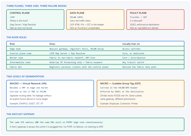
What Are the Three Planes of an SD-Access Fabric?
What does each plane contribute?
LISP is the control plane and answers "where is this host". Edge nodes register the endpoints they see with a control plane node acting as a Map Server, and query it as a Map Resolver when they need to reach an endpoint they do not know. VXLAN is the data plane and carries the traffic in a tunnel between edge nodes, with the virtual network identifier and the group tag in the header. TrustSec is the policy plane and decides, at the destination, whether traffic carrying that group tag is permitted to reach the destination's group.
A Deeper Dive into the Planes
Why separating location from identity matters
A traditional network encodes location in the address: a host's subnet says where it is, and moving it means renumbering it or extending the VLAN. LISP separates the two — the endpoint identifier is the host's address, the routing locator is the switch it is currently attached to, and a mapping between them lives in a database that is queried on demand. That is what makes a host's subnet independent of its physical location, and it is the single property that most of SD-Access's benefits derive from.
! The control plane database, viewed on a control plane node
CP1# show lisp instance-id 4099 ipv4 server
LISP Site Registration Information
Site Name      Last      Up  Who Last              Inst  EID Prefix
               Register      Registered            ID
site_uci       00:00:41  yes 10.1.1.5              4099  10.10.10.55/32
site_uci       00:00:12  yes 10.1.1.6              4099  10.10.10.71/32
! ^ EID = the host. Who Registered = the edge node (RLOC).
!
! And the same view from an edge node's local cache
EDGE1# show lisp instance-id 4099 ipv4 map-cache
LISP IPv4 Mapping Cache for LISP 0 EID-table vrf CAMPUS, 2 entries
10.10.10.71/32, uptime: 00:04:12, expires: 23:55:47, via map-reply
  Locator   Uptime    State  Pri/Wgt
  10.1.1.6  00:04:12  up     10/10
VXLAN, and the one thing it adds
VXLAN in SD-Access is not plain VXLAN. The Group Policy Option extends the header with a 16-bit field carrying the source's scalable group tag, so that policy information travels with the packet rather than being re-derived at the destination. That is why enforcement can happen at the far edge node without that node needing to know anything about the source beyond what arrived in the header, and it is why the data plane and the policy plane are genuinely coupled in this design.
! What the encapsulation costs
! Original Ethernet frame
!   + VXLAN header      8 bytes  (VNI + Group Policy ID)
!   + UDP header        8 bytes  (destination port 4789)
!   + Outer IP header   20 bytes
!   + Outer Ethernet    14 bytes
!   = 50 bytes of overhead
!
! Which is why the underlay MTU matters
EDGE1# show interfaces TenGigabitEthernet1/1/1 | include MTU
  MTU 9100 bytes, BW 10000000 Kbit/sec
! ^ 9100 is the recommended underlay value. 1500 will
!   pass small packets and fail on real traffic.
TrustSec, and where enforcement happens
Enforcement is at the destination, not the source. The source edge node tags the traffic with the source's group; the destination edge node looks up the policy matrix for that source group against the destination group and permits or denies. This means an SGACL that is not downloaded to the destination switch does not enforce, regardless of what the policy matrix says, and it means a denial appears at the far end of the fabric from where the traffic entered.
! What policy has actually been downloaded to this switch
EDGE2# show cts role-based permissions
IPv4 Role-based permissions default: Permit IP-00
IPv4 Role-based permissions from group 10:Employees to group 20:Printers:
        Printer_Access-10
IPv4 Role-based permissions from group 30:Contractors to group 20:Printers:
        Deny IP-00
!
! Which SGT is a given host actually carrying?
EDGE1# show cts role-based sgt-map vrf CAMPUS all
IP Address    SGT   Source
10.10.10.55   10    LOCAL
10.10.10.71   30    LOCAL
!
! And the enforcement counters
EDGE2# show cts role-based counters
Which plane is failing
| Symptom | Plane | First command | Common cause |
|---|---|---|---|
| Host not reachable, no map-cache entry | Control | show lisp ... server |
Registration failed — host not learned, or CP unreachable |
| Map-cache entry exists, traffic fails | Data | show ip route on the underlay |
Underlay path or MTU |
| Small packets work, large ones fail | Data | show interfaces \| include MTU |
Underlay MTU below 9100 |
| Reachable, then denied | Policy | show cts role-based permissions |
SGACL, or an unexpected SGT assignment |
| Works in one VN, not between two | Design | show vrf on the border |
No fusion device — VNs are separate by design |
What Are the Node Roles and Where Does Each Belong?
What are the roles?
Five that matter. Edge nodes are the access switches, host the anycast gateway, and register endpoints. Control plane nodes run the LISP Map Server and Map Resolver. Border nodes connect the fabric to everything outside it. Intermediate nodes forward underlay IP and are entirely fabric-unaware. And the fabric-enabled wireless LAN controller registers wireless clients with the control plane without ever appearing in the data path. Roles are functions rather than devices, and one physical switch frequently carries several.
A Deeper Dive into the Roles
Edge nodes and the anycast gateway
Every edge node in a fabric configures the same SVI address and the same MAC address for a given subnet. A host's default gateway is therefore always the switch it is plugged into, and moving that host to a different switch changes nothing it can observe — no ARP refresh, no gateway change, no FHRP failover. This is why SD-Access removes the first hop redundancy problem rather than solving it: there is no single router owning the address to fail over from.
! The anycast gateway, identical on every edge node
interface Vlan1021
 description Configured from Catalyst Center
 mac-address 0000.0c9f.f001
 vrf forwarding CAMPUS
 ip address 10.10.10.1 255.255.255.0
 ip helper-address 10.5.5.5
 no ip redirects
 ip route-cache same-interface
 no lisp mobility liveness test
 lisp mobility 10_10_10_0-CAMPUS-IPV4
!
! Every edge node has this. Byte for byte the same.
EDGE1# show run interface Vlan1021 | include address
EDGE2# show run interface Vlan1021 | include address
Control plane nodes, and why there are usually two
A control plane node holds the endpoint database and answers every lookup for hosts an edge node does not already know. Losing it does not immediately break the fabric — existing map-cache entries continue to work until they expire — but it breaks every new conversation. Two control plane nodes are standard, and they operate independently rather than as an active-standby pair, with edge nodes registering to both.
! An edge node's view of its control plane nodes
EDGE1# show lisp instance-id 4099 ipv4 map-resolver
    Map-resolver         Uptime     State
    10.1.100.1           4d02h      up
    10.1.100.2           4d02h      up
!
! Registration health, which is what actually matters
EDGE1# show lisp instance-id 4099 ipv4 database
LISP ETR IPv4 Mapping Database for EID-table vrf CAMPUS
Entries total 2, no-route 0, inactive 0
10.10.10.55/32, dynamic-eid 10_10_10_0-CAMPUS-IPV4, inherited from default
  Locator  Pri/Wgt  Source     State
  10.1.1.5  10/10   cfg-intf   site-self, reachable
!
CP1# show lisp instance-id 4099 ipv4 server summary
Border nodes and the three flavours
A border node is where the fabric ends. An internal border connects to known prefixes — a data centre, a shared services block — and imports those specific routes into the fabric. An external border is the default exit for everything the fabric does not know, and does not need to import anything. An anywhere border does both, which is the common configuration in a single-site fabric where one pair of devices connects to everything.
| Border type | Advertises into the fabric | Typical connection | Registers with control plane |
|---|---|---|---|
| Internal | Specific known prefixes | Data centre, shared services | Yes — as the path to those prefixes |
| External | A default route only | WAN, internet edge | No — it is the catch-all |
| Anywhere | Both | One pair connecting to everything | Yes, for the known prefixes |
Intermediate nodes, which do nothing fabric-specific
An intermediate node is a switch in the underlay path that forwards routed IP between fabric nodes and has no fabric configuration at all. It does not need to support VXLAN, does not appear in the control plane, and does not need to be managed by the controller. It does need two things: enough MTU to carry the encapsulated frames, and, if the fabric uses native multicast, PIM in the underlay. Those two requirements are the entire fabric-related burden on an intermediate node.
Fabric wireless, which changes the data path
In a fabric-enabled wireless deployment the access point builds a VXLAN tunnel to the edge node it is attached to, and wireless traffic is decapsulated there rather than being tunnelled back to a controller. The controller remains in the control path — it registers clients with the control plane node — and leaves the data path entirely. That is the significant change relative to a traditional central-switching design, and it means wireless traffic gets the same anycast gateway, the same VN and the same SGT enforcement as wired traffic on the same switch.
! Wireless clients appear in the same database as wired
CP1# show lisp instance-id 4099 ipv4 server | include 10.10.20
site_uci  00:00:22  yes  10.1.1.5  4099  10.10.20.44/32
! ^ Registered by an EDGE node, not by the WLC.
!
! The AP itself lives in the infrastructure VN
EDGE1# show access-tunnel summary
EDGE1# show wireless fabric summary
How Do Virtual Networks and SGTs Divide the Fabric?
What is the difference?
A virtual network is a routing boundary: it becomes a VRF on every edge and border node, it has its own routing table, and traffic does not cross between VNs without an explicit device configured to do so. A scalable group tag is a policy boundary inside a VN: two hosts can be in the same subnet with the same gateway and different SGTs, and a policy between those groups permits or denies traffic without any routing separation at all. Macro and micro, and choosing the wrong one for a requirement is the most common design error in a first fabric.
A Deeper Dive into Segmentation
When to use a VN
A VN is the right answer when two populations must not share a routing table — a guest network that must never see corporate prefixes, an OT environment with a regulatory separation requirement, a merged company's address space that overlaps yours. It is a heavy boundary: crossing it requires a fusion device or explicit route leaking, and every VN adds a VRF, a set of routing adjacencies at the border handoff, and configuration on every border.
! What a VN becomes on an edge node
EDGE1# show vrf
  Name       Default RD       Protocols   Interfaces
  CAMPUS     1:4099           ipv4,ipv6   Vl1021, Vl1022, LISP0.4099
  GUEST      1:4100           ipv4,ipv6   Vl1031, LISP0.4100
  IOT        1:4101           ipv4,ipv6   Vl1041, LISP0.4101
!
! Each VN has its own instance ID = its own L3 VNI
EDGE1# show lisp instance-id 4100 ipv4 database | include EID-table
LISP ETR IPv4 Mapping Database for EID-table vrf GUEST
When to use an SGT
An SGT is the right answer when two populations share a routing context and need different permissions — employees and contractors on the same floor and the same subnet, printers that should accept jobs and originate nothing, cameras that should reach only the recording server. It costs nothing in routing terms, applies regardless of subnet, and follows the host when it moves because the tag is assigned at authentication rather than derived from the address.
! SGT assignment sources, in order of usefulness
!  1. Dynamic from ISE at 802.1X or MAB authentication
!  2. Static IP-to-SGT binding, for devices that cannot authenticate
!  3. Subnet-to-SGT, as a coarse fallback
!  4. Port-based, for a trusted uplink
!
! A static binding for something that cannot do 802.1X
cts role-based sgt-map vrf CAMPUS 10.10.40.50 sgt 50
!
! Verify the assignment and its source
EDGE1# show cts role-based sgt-map vrf CAMPUS all
IP Address     SGT    Source
10.10.10.55    10     INTERNAL
10.10.10.71    30     LOCAL
10.10.40.50    50     CLI
! ^ Source tells you whether ISE assigned it or a human did.
The choice, stated plainly
| Requirement | Use | Why |
|---|---|---|
| Guests must never reach corporate | VN | Separate routing table — the prefixes are not present |
| Overlapping address space | VN | Only a VRF makes duplicate prefixes legal |
| Regulatory separation of OT | VN | Auditable as a routing boundary |
| Contractors restricted from finance servers | SGT | Same routing context, different permissions |
| Printers must not initiate connections | SGT | Applies regardless of which subnet they land in |
| Cameras reach only the recorder | SGT | Policy follows the device as it moves |
Crossing between VNs
Two VNs do not communicate by default and that is the point of them. Where a shared service — DNS, DHCP, a certificate authority — must be reachable from several VNs, the standard answer is a fusion device: a router or firewall outside the fabric with an interface in each VN, leaking the specific prefixes that need to cross. A firewall is the better choice because the crossing point is exactly where policy belongs, and because the alternative of route leaking on the border tends to grow into an unauditable set of exceptions.
! Fusion device: a VRF per VN, leaking only what must cross
! On the fusion router (outside the fabric)
vrf definition CAMPUS
 rd 65000:4099
 address-family ipv4
  route-target export 65000:4099
  route-target import 65000:4099
  route-target import 65000:9000
 exit-address-family
!
vrf definition SHARED
 rd 65000:9000
 address-family ipv4
  route-target export 65000:9000
  route-target import 65000:4099
  route-target import 65000:4100
 exit-address-family
! ^ CAMPUS and GUEST both reach SHARED. Never each other.
How Do I Get Traffic In and Out of the Fabric?
What happens at the border?
The border node de-encapsulates VXLAN and hands traffic to the outside world using ordinary routing, one routing context per virtual network. In practice that means a VRF-lite handoff: an 802.1Q sub-interface per VN on the link to the next device, with a routing adjacency per VN across it. The group tag, which was in the VXLAN header, has nowhere to live in an ordinary IP packet, so it is carried onward either by inline tagging where the next device supports it or by SXP where it does not.
A Deeper Dive into the Handoff
The VRF-lite handoff
Each VN becomes a sub-interface with its own VLAN tag, its own addressing and its own BGP session. This is why VN count drives border complexity directly: three VNs is three sub-interfaces and three BGP sessions per border per uplink, and ten VNs is ten of each. It is entirely conventional configuration, which is an advantage — the device on the far side of the handoff needs to know nothing about the fabric.
! Border handoff - one sub-interface and one peer per VN
interface TenGigabitEthernet1/0/1.3001
 description CAMPUS VN handoff
 encapsulation dot1Q 3001
 vrf forwarding CAMPUS
 ip address 10.200.1.1 255.255.255.252
!
interface TenGigabitEthernet1/0/1.3002
 description GUEST VN handoff
 encapsulation dot1Q 3002
 vrf forwarding GUEST
 ip address 10.200.1.5 255.255.255.252
!
router bgp 65100
 address-family ipv4 vrf CAMPUS
  neighbor 10.200.1.2 remote-as 65000
  neighbor 10.200.1.2 activate
 exit-address-family
 address-family ipv4 vrf GUEST
  neighbor 10.200.1.6 remote-as 65000
  neighbor 10.200.1.6 activate
 exit-address-family
Carrying the SGT beyond the border
Inline tagging puts the group tag in a Cisco metadata field in the Ethernet frame and requires the next device to understand it. SXP is a TCP-based protocol that carries IP-to-SGT bindings out of band, so the receiving device can apply policy without the tag being in the packet at all. Inline is preferable where supported because it is per-packet and needs no state; SXP exists because a great deal of equipment does not support inline tagging.
! Inline tagging on a link between capable devices
interface TenGigabitEthernet1/0/2
 cts manual
  policy static sgt 2 trusted
!
! SXP where the far end cannot do inline tagging
cts sxp enable
cts sxp default password 7 08351F1B
cts sxp default source-ip 10.1.1.1
cts sxp connection peer 10.9.9.9 password default mode local speaker
!
! Verify what is being exported
BORDER1# show cts sxp connections brief
Peer_IP     Source_IP  Conn Status   Duration
10.9.9.9    10.1.1.1   On            4:02:18:41
!
BORDER1# show cts sxp sgt-map brief
Multi-site: IP transit or SD-Access transit
Connecting two fabrics has two answers with different properties. IP transit hands off at each border into an ordinary routed network, which means the VN separation survives as VRF-lite and the SGT has to be carried by SXP or inline tagging across whatever is in between. SD-Access transit keeps the traffic encapsulated between sites and preserves both the VN and the SGT natively, at the cost of requiring a transit control plane node and a transit network that can carry the encapsulation.
| Property | IP transit | SD-Access transit |
|---|---|---|
| VN preserved | As VRF-lite, reconfigured per hop | Natively |
| SGT preserved | Only via SXP or inline tagging | Natively, in the header |
| Transit network requirement | Any IP network | Must carry the encapsulation and MTU |
| Extra components | None | Transit control plane node |
| Suits | Existing WAN, third-party transit | Owned transit between campuses |
Layer 2 handoff and its limits
A border can also extend a fabric subnet out as a plain VLAN, which exists for migration and for appliances that genuinely need Layer 2 adjacency to something outside the fabric. It works and it reintroduces exactly the properties the fabric was built to remove: a broadcast domain crossing the boundary, spanning tree relevance, and a subnet whose location is once again meaningful. It is a migration tool rather than a design element.
DHCP, which needs one extra thing
Because every edge node presents the same anycast gateway address, a DHCP relay from an edge node would give the server no way to tell which switch the request came from — and therefore no way to select the correct scope in a fabric where one subnet spans many switches. SD-Access adds the edge node's identity into the relayed request so the server can respond correctly, which is why fabric DHCP works with standard servers but is not quite standard relay behaviour.
! The relay is configured on the anycast SVI
interface Vlan1021
 ip helper-address 10.5.5.5
 ip dhcp relay source-interface Loopback0
! ^ The loopback is unique per edge node, which is what
!   lets the server distinguish one switch from another.
!
! Verify bindings are landing where expected
EDGE1# show ip dhcp snooping binding
EDGE1# show device-tracking database vlanid 1021
Which SD-Access Design Decisions Are Hard to Reverse?
What should be decided carefully?
Four things. The underlay addressing and MTU, because changing them later touches every device. The virtual network list, because each one grows a border handoff and a fusion-device exception. The subnet-to-VN mapping, because moving a subnet between VNs means renumbering or a maintenance window per host. And whether multicast is head-end replicated or native, because native requires PIM everywhere in the underlay and retrofitting it is a change to every intermediate node.
A Deeper Dive into the Irreversible Decisions
MTU, which has to be right from the start
show interfaces \| include MTU on the underlay links, and a ping with the do-not-fragment bit set at increasing sizes to locate the threshold. Fix: set the underlay MTU to 9100 on every fabric and intermediate link before any endpoint is onboarded — including on devices the controller does not manage.The virtual network list
Multicast, decided once
A pre-deployment checklist
! Verify before onboarding a single endpoint
show interfaces | include MTU
! ^ 9100 on every underlay link, including unmanaged ones
show ip route | include /32
! ^ every fabric node's loopback reachable from every other
ping <remote-loopback> source Loopback0 size 9000 df-bit
! ^ the definitive MTU test, end to end
show ip pim interface
! ^ if native multicast is planned, PIM everywhere in the path
show cts environment-data
! ^ the switch has reached ISE and downloaded the SGT list
show lisp instance-id <id> ipv4 map-resolver
! ^ both control plane nodes reachable from every edge
Layer 2 flooding, which is off for a reason
A fabric does not flood broadcast and unknown unicast by default, because the control plane knows where every endpoint is and flooding is therefore unnecessary. Some devices depend on that flooding anyway — silent hosts that never speak until spoken to, appliances using non-IP discovery, older building systems — and Layer 2 flooding can be enabled per subnet to accommodate them. It requires native multicast in the underlay, and it reintroduces broadcast traffic that the fabric was designed to eliminate.
The right approach is to identify these devices during discovery rather than after cutover, because the symptom of a silent host in a non-flooding fabric is a device that simply never appears and gives no indication why. Enabling flooding for one subnet containing those devices is a considerably better outcome than enabling it broadly to make an unidentified problem go away.
What to instrument on day one
Three things that are cheap to add early and awkward to retrofit. Endpoint registration counts per edge node, which reveal a switch that has stopped registering before users report it. Underlay reachability between every pair of fabric loopbacks, because the data plane depends entirely on it and nothing else tests it. And SGACL denial counters, because a policy change that denies more than intended is otherwise discovered by a helpdesk ticket rather than by a graph.
Blueprint framing
The CCIE Enterprise Infrastructure v1.1 blueprint places SD-Access in the software-defined architecture domain, and the questions tend to be architectural rather than command-level: which node role does what, what the control plane and data plane protocols are, how VNs and SGTs differ, and what a border hands off. Being able to state the three planes and their protocols, and to explain the difference between macro and micro segmentation, covers a large proportion of what that domain asks.
Conclusion
SD-Access is best understood as three independent planes rather than as a product. LISP answers where a host is, VXLAN carries traffic there, and TrustSec decides whether it is allowed — and each fails in a way the other two do not. A host that is not found, a host that is found and unreachable, and a host that is reachable and denied are three different problems with three different first commands, and identifying which one you have eliminates most of the search space immediately.
The design decisions that matter are mostly about segmentation and mostly made too generously. A virtual network is a routing boundary that costs a handoff at every border and an exception at every fusion point; a scalable group tag is a permissions boundary that costs nothing structurally and follows the host as it moves. Requirements phrased as "these users must not reach those servers" are almost always SGT requirements, and implementing them as VNs is the error that produces a border configuration nobody wants to touch.
Finally, the underlay. Every tunnel in the fabric rides on ordinary routed IP between loopbacks, and an MTU below 9100 anywhere in that path produces failures that look like anything except an MTU problem. Getting the underlay addressing, MTU and multicast mode right before onboarding endpoints is not preparation for the deployment — for the majority of fabrics that run into trouble, it is the deployment.
External Links
- RFC 6830 — The Locator/ID Separation Protocol (LISP)
- RFC 9300 — The Locator/ID Separation Protocol (LISP)
- RFC 7348 — Virtual eXtensible Local Area Network (VXLAN)
- Cisco Design Zone — Campus Wired and Wireless Design Guides
- Cisco — Software-Defined Access Configuration Guide, Catalyst 9300
- Cisco TrustSec Configuration Guide
- Cisco Learning Network — CCIE Enterprise Infrastructure
Reference Notes
- RFC 6830 defines the Locator/ID Separation Protocol, separating an endpoint identifier from the routing locator that describes where the endpoint currently attaches.
- RFC 9300 is the standards-track specification of LISP, defining the Map Server and Map Resolver functions that SD-Access control plane nodes perform.
- RFC 7348 defines VXLAN, including the 8-byte VXLAN header, the 24-bit VXLAN Network Identifier, and UDP destination port 4789.
- Cisco documentation describes the Group Policy Option extension to the VXLAN header, which carries a 16-bit group policy identifier used for Scalable Group Tag propagation.
- Cisco documentation gives the total VXLAN encapsulation overhead as 50 bytes for an IPv4 underlay, which is the basis for the recommended underlay MTU.
- Cisco SD-Access design guidance recommends an underlay MTU of 9100 bytes on fabric and intermediate links to accommodate the encapsulation without fragmentation.
- Cisco documentation describes the fabric node roles: edge node, control plane node, border node, intermediate node, and fabric-enabled wireless LAN controller.
- Cisco documentation describes the anycast gateway, in which the same SVI IP address and MAC address are configured on every fabric edge node for a given subnet.
- Cisco documentation distinguishes internal, external and anywhere border nodes by whether they advertise specific known prefixes, a default route, or both into the fabric.
- Cisco TrustSec documentation describes SGACL enforcement at the destination, using the source group tag carried with the traffic and the destination group of the receiving endpoint.
- Cisco TrustSec documentation describes both inline tagging, which carries the SGT within the Ethernet frame, and SXP, which conveys IP-to-SGT bindings over TCP to devices that cannot perform inline tagging.
- The CCIE Enterprise Infrastructure v1.1 unified exam topics include SD-Access within the software-defined infrastructure domain, covering fabric design, roles and components.