

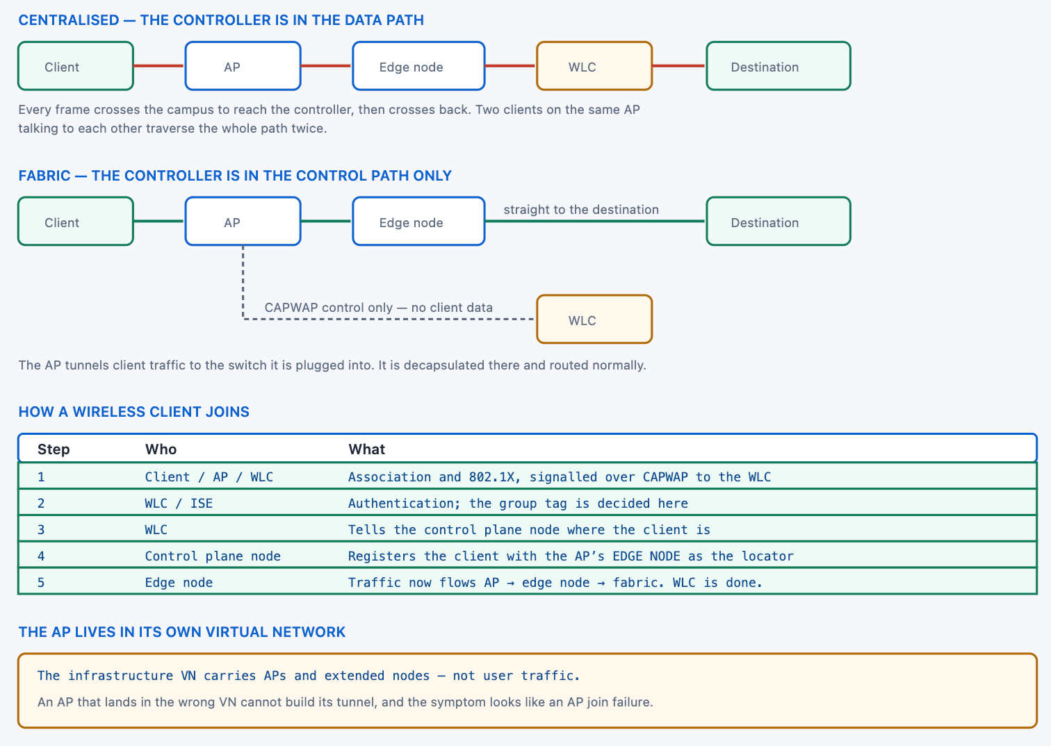
Wireless in a fabric is the clearest example of what the architecture is actually for. In a traditional centralised design, every wireless frame travels from the access point to a controller and back out again, which means the controller sits in the data path of traffic that may never have needed to go anywhere near it. Two clients on the same access point talking to each other send their traffic across the campus twice.
Fabric wireless removes the controller from that path entirely. The access point still talks to the controller — for radio management, authentication signalling, and everything else a controller does — but client traffic goes into a tunnel to the switch the access point is plugged into and is decapsulated there. The controller keeps every control-plane responsibility and loses its data-plane one, which is the decoupling the design is named for.
This article covers what that decoupling means in practice, how a wireless client is onboarded and registered, why roaming needs no mobility tunnel between controllers, how to design and size a deployment, and the failures that present as wireless problems and are actually fabric problems — starting with the access point that cannot build its tunnel because it landed in the wrong virtual network.
What Does Decoupling the Control Plane From the Data Plane Mean?
What actually moves?
The data path, and only the data path. The controller still handles radio resource management, client association signalling, authentication, roaming coordination and every configuration function it has always handled. What it stops doing is carrying client traffic. The access point builds a separate tunnel for that traffic to the switch it is connected to, and the switch treats what emerges exactly as it would treat traffic from a wired port on the same subnet.
A Deeper Dive into the Decoupling
Why the traditional path is expensive
In a centralised design the controller is a single point through which all wireless traffic passes, which makes it a bandwidth constraint, a latency contributor and a failure domain covering every wireless client at once. None of those is a defect — it is the consequence of a design that centralises forwarding to centralise policy. Fabric wireless keeps the centralised policy and removes the centralised forwarding, because the policy now travels in the packet header rather than being applied at a chokepoint.
! What the edge node sees - a tunnel from each attached AP
EDGE1# show access-tunnel summary
Access Tunnels General Statistics:
  Number of AccessTunnel Data Tunnels = 3
!
Name   RLOC IP(Source)  AP IP(Destination)  VRF ID  Source Port
------ ------------     ------------------  ------  -----------
Ac0    10.1.1.5         10.200.10.21        0       N/A
Ac1    10.1.1.5         10.200.10.22        0       N/A
Ac2    10.1.1.5         10.200.10.23        0       N/A
! ^ Three APs, three tunnels, all terminating on this switch.
The wireless client is an ordinary fabric endpoint
Once its traffic emerges from the tunnel at the edge node, a wireless client is indistinguishable from a wired one. Same anycast gateway, same virtual network, same group tag, same policy enforcement, same registration in the mapping system. That uniformity is the real product of the design: a policy written for a user applies identically whether they are at a desk or on a laptop across the building, without any wireless-specific configuration expressing it.
! Wireless clients appear in the same places as wired ones
EDGE1# show device-tracking database vlanid 1021 | include 10.10.10
EDGE1# show lisp instance-id 4099 ipv4 database | count /32
EDGE1# show cts role-based sgt-map vrf CAMPUS all
!
! Nothing in these outputs distinguishes wired from wireless.
! That is the point.
!
! Where the distinction IS visible
EDGE1# show wireless fabric summary
EDGE1# show access-tunnel summary
What the controller still owns
| Function | Centralised design | Fabric design |
|---|---|---|
| Radio resource management | Controller | Controller |
| Client association signalling | Controller | Controller |
| Authentication signalling | Controller | Controller |
| Roaming coordination | Controller | Controller |
| AP configuration and image | Controller | Controller |
| Client data forwarding | Controller | Edge node |
| Client registration in the fabric | N/A | Controller informs the control plane node |
What this does to east-west wireless traffic
The clearest illustration is two clients on the same access point. In a centralised design their traffic travels to the controller and back — across the access layer, the distribution, possibly the core, twice — for a conversation between two devices in the same room. In a fabric it travels to the edge node, is routed, and comes straight back out, which is one switch hop each way.
That case is not hypothetical. Screen sharing, local file transfers, printing, and increasingly video between colleagues in the same space are all east-west wireless traffic, and in a busy building they represent a substantial fraction of the total. Removing the round trip does not just reduce latency for those flows; it removes their load from every link between the access layer and the controller.
Over-the-top, which is a migration state
A fabric can also carry traditional centralised wireless as ordinary traffic — the controller and access points behave exactly as they always did, and the fabric is just the transport underneath. This is a legitimate step where the wireless equipment is not fabric-capable or where the wireless team is not ready, and it delivers none of the benefits above. It is worth naming explicitly in a design so that nobody later assumes the wireless is integrated when it is merely carried.
How Does a Wireless Client Get Onto the Fabric?
What is the sequence?
The access point must be onboarded first: it obtains an address in the infrastructure virtual network, joins the controller, and is provisioned as a fabric access point, at which point it builds its tunnel to the edge node. Then a client associates, authenticates through the controller, and the controller tells the control plane node where that client is — naming the access point's edge node as the locator. From that moment the client is a registered fabric endpoint and its traffic takes the direct path.
A Deeper Dive into Onboarding
The infrastructure virtual network
Access points do not live in a user virtual network. They live in a dedicated infrastructure VN alongside extended nodes, which keeps management traffic separate from user traffic and means an access point cannot reach user subnets directly. An access point that receives an address from the wrong pool cannot establish its tunnel, and the symptom is an access point that appears to join the controller and then does nothing useful.
! The AP's address should come from the infrastructure pool
EDGE1# show device-tracking database | include 10.200.10
ARP 10.200.10.21   00ab.cdef.1234  Gi1/0/45  3999  0025  REACHABLE
! ^ VLAN 3999 is the infrastructure VN in this example.
!
! And the port should be configured for an AP, not a user
EDGE1# show run interface GigabitEthernet1/0/45
interface GigabitEthernet1/0/45
 description Fabric AP
 switchport access vlan 3999
 switchport mode access
 device-tracking attach-policy IPDT_POLICY
 no access-session port-control
 spanning-tree portfast
The access point tunnel
Once the access point has an address and has joined the controller, it builds a tunnel to the edge node it is plugged into. That tunnel carries client traffic and terminates locally, which is why the edge node must be the switch the access point is physically connected to — there is no arrangement where an access point tunnels to a distant edge node in normal operation.
! Confirm the AP is registered as a fabric AP
WLC# show wireless fabric summary
Fabric Status : Enabled
!
Control-plane:
Name          IP-address     Key       Status
default-control-plane 10.1.100.1  <key>  Up
!
Fabric VNID Mapping:
  Name    L2-VNID  L3-VNID  IP Address        Subnet
  CAMPUS  8188     4099     10.10.10.0        255.255.255.0
!
WLC# show ap summary
WLC# show ap name AP-3F-01 config general | include Fabric|IP Address
Client registration, performed by the controller
The client does not register itself and the edge node does not register it either. The controller, which knows the client has authenticated and knows which access point it is on, informs the control plane node — and the locator recorded is the edge node that access point is attached to. This is the one place where the wireless control path and the fabric control plane meet, and it is where a client that authenticates successfully and remains unreachable has usually failed.
! The controller's view of fabric-registered clients
WLC# show wireless fabric client summary
Number of Fabric Clients : 412
!
MAC Address    AP Name     WLAN State    Protocol Method
a0b4.0103.9999 AP-3F-01    3    Run      11ax(5)  Dot1x
!
! And the control plane node's record of the same client
CP1# show lisp instance-id 4099 ipv4 server 10.10.10.99/32
  Site name: site_uci
  Registered: yes
  Registered via: 10.1.1.5
! ^ 10.1.1.5 is the EDGE NODE, not the WLC.
Where the group tag comes from
Exactly where it comes from for a wired client — the authentication response. The controller receives it and it ends up as a binding at the edge node, so wireless traffic carries the same tag a wired session for the same user would carry. That is what makes a single policy matrix cover both, and it is why a wireless-specific policy is almost never necessary.
! The tag on a wireless client, at the edge node
EDGE1# show cts role-based sgt-map vrf CAMPUS 10.10.10.99
IP Address     SGT   Source
10.10.10.99    10    LOCAL
! ^ Identical in form to a wired client's binding.
!
! And the controller's view of the same assignment
WLC# show wireless client mac-address a0b4.0103.9999 detail | include SGT|VN
Order of operations during a rollout
Access points before clients, and the infrastructure virtual network before access points. A site where the infrastructure pool is not defined, or where access ports have not been configured for it, produces access points that obtain user addresses and then behave in confusing ways — they join the controller and appear healthy, which makes the underlying problem hard to see.
The sequence that avoids this is to define the infrastructure virtual network and its pool, configure the access ports for it, confirm one access point obtains the right address and builds its tunnel, and only then onboard the rest. Verifying one access point end to end takes minutes and validates every step for all of them.
! Validate ONE access point completely before doing forty
!
! 1. Right address, right VLAN
EDGE1# show device-tracking database | include 10.200.10.21
!
! 2. Joined the controller
WLC# show ap summary | include AP-3F-01
!
! 3. Tunnel built to the edge node
EDGE1# show access-tunnel summary | include 10.200.10.21
!
! 4. A test client on it reaches the fabric
CP1# show lisp instance-id 4099 ipv4 server <client-ip>/32
!
! Only when all four pass, roll out the rest.
Guest, which usually gets its own path
Guest traffic is normally placed in its own virtual network so that it cannot reach corporate prefixes at all, and in larger deployments it may use dedicated border and control plane nodes so that guest traffic never enters the corporate fabric's control plane. Both are ordinary applications of the segmentation model rather than wireless-specific mechanisms, which is the point — guest isolation is a virtual network decision, not a wireless one.
How Does Roaming Work Without a Mobility Tunnel?
What happens when a client moves?
The client associates to a new access point, the controller notices, and if that access point is on a different edge node the controller updates the client's locator in the mapping system. Remote nodes holding a stale entry are told to refresh. The client's address is unchanged, its gateway is unchanged because the anycast gateway is identical everywhere, and no tunnel is built between anything to accommodate the move.
A Deeper Dive into Roaming
Why the traditional problem does not arise
In a centralised design, a client roaming between controllers needs its traffic tunnelled back to its original controller so that its address and session remain valid — the anchor mechanism. That exists because the client's subnet is tied to a controller. In a fabric the subnet is not tied to anything: it exists identically on every edge node, so a client that moves has simply moved, and the only thing that needs updating is a database entry.
! Before the roam - client on EDGE1's AP
CP1# show lisp instance-id 4099 ipv4 server 10.10.10.99/32
  Registered via: 10.1.1.5
!
! After roaming to an AP on EDGE3
CP1# show lisp instance-id 4099 ipv4 server 10.10.10.99/32
  Registered via: 10.1.1.12
  Last registered: 00:00:03
! ^ Same client, same address, different locator.
!   No tunnel was built. No anchor exists.
Intra-edge and inter-edge roams
A client moving between two access points on the same edge node changes nothing in the fabric at all — the locator is the same switch, so no registration update is needed and the roam is entirely a wireless-layer event. A move to an access point on a different edge node updates the locator. Distinguishing the two matters when investigating, because only the second kind can produce fabric-related roaming symptoms.
! Which edge node is each AP on? This decides roam type.
EDGE1# show access-tunnel summary | include 10.200.10
EDGE3# show access-tunnel summary | include 10.200.10
!
! And the AP-to-switch mapping from the controller
WLC# show ap summary | include AP-3F
WLC# show ap name AP-3F-01 config general | include Switch|Port
!
! A roam between APs listed on the SAME edge node
! involves no fabric state change whatsoever.
What can still go slowly
The fabric side of a roam is a database update and is fast. What remains is everything that was always part of roaming: the client's own decision to move, the authentication exchange if fast transition is not in use, and the radio-layer handoff. A roaming problem in a fabric is therefore usually a wireless problem — which is a useful conclusion, because it directs the investigation to the radio side rather than to the fabric.
| Roam stage | Owned by | Typical cost | If slow, look at |
|---|---|---|---|
| Client decides to move | The client | Highly variable | Client behaviour, RF design |
| Association to the new AP | Wireless layer | Milliseconds | RF, channel utilisation |
| Re-authentication | Controller and ISE | Tens of ms with fast transition | Fast transition configuration |
| Locator update | Controller and CP node | Milliseconds | Control plane reachability |
| Remote cache refresh | Fabric control plane | Milliseconds | Rarely the problem |
How Do I Design and Size a Fabric Wireless Deployment?
What changes about sizing?
Two things. Edge nodes now carry wireless clients as well as wired ones, so their endpoint count is the sum rather than the port count. And the controller stops being a throughput consideration, because it carries no client traffic — its sizing is about association counts, access point counts and control-plane events, not about gigabits. Both are straightforward and both are routinely got wrong in the same direction: edge nodes under-sized, controllers over-sized.
A Deeper Dive into Design
Counting endpoints per edge node properly
A closet with two hundred ports and four access points serving forty clients each is carrying three hundred and sixty endpoints. In a modern campus the wireless half is frequently the larger one, and sizing against port count alone therefore understates the load by more than half. The three counts to check are the tracking database, the mapping database and the group bindings, and they should be checked on the busiest closet rather than an average one.
! The real endpoint count on an edge node
EDGE1# show device-tracking database | count REACHABLE
EDGE1# show lisp instance-id 4099 ipv4 database | count /32
EDGE1# show cts role-based sgt-map vrf CAMPUS all | count LOCAL
!
! How many of those arrived wirelessly
EDGE1# show access-tunnel summary | include Number
  Number of AccessTunnel Data Tunnels = 4
WLC# show ap summary | include AP-1F | count
!
! And the hardware headroom behind it all
EDGE1# show platform hardware fed switch active fwd-asic resource tcam utilization
Where the controller sits
The controller does not need to be inside the fabric and frequently is not — it can sit outside, reachable through the border, because it needs reachability to access points and to the control plane node rather than a position in the data path. That freedom is useful: it means an existing controller in a data centre can serve a new fabric without being relocated, and it means controller redundancy is designed on its own terms rather than around fabric roles.
! The controller needs reachability, not a fabric role
!
! From the WLC: can it reach the control plane node?
WLC# ping 10.1.100.1
WLC# show wireless fabric summary | include Status
!
! From an edge node: can the APs reach the WLC?
EDGE1# ping vrf INFRA_VN 10.50.50.10
EDGE1# show device-tracking database | include 10.200.10
!
! And the AP's own view
WLC# show ap name AP-3F-01 config general | include Controller|Join
MTU on the access point's link
The tunnel from the access point to the edge node adds encapsulation just as the fabric's own does, so the link between them needs headroom too. This is easy to miss because it is an access port rather than an underlay link, and the switch template that raises MTU on uplinks may not touch access ports. The symptom is the familiar one — small packets fine, large ones lost — occurring only for wireless clients on that access point.
! The AP's access port needs MTU headroom too
EDGE1# show interfaces GigabitEthernet1/0/45 | include MTU
  MTU 9100 bytes, BW 1000000 Kbit/sec
!
! System-wide setting on the switch
EDGE1# show system mtu
System MTU size is 9198 bytes
!
! Test from a wireless client, not from the switch
!   ping <destination> -s 1472 -M do     (Linux)
!   ping <destination> -f -l 1472        (Windows)
Infrastructure pool sizing
Access points and extended nodes share the infrastructure virtual network's address pool, and it needs to hold every one of them across the site with room for growth. It is a pool that is easy to size for the initial access point count and awkward to extend later, for the same reason the loopback pool is: a second range means a second summary in every place the first one is referenced.
A design checklist
| Item | Check | Common error |
|---|---|---|
| Edge node endpoint count | Wired plus wireless, busiest closet | Sized on port count alone |
| Infrastructure pool | All APs and extended nodes, plus growth | Sized for initial AP count |
| AP access port MTU | Raised, like the uplinks | Template covers uplinks only |
| Controller reachability | To APs and to the control plane node | Assumed rather than tested |
| Guest separation | Its own virtual network | Guest placed in a corporate VN |
| Fast transition | Enabled where roaming matters | Left off, then blamed on the fabric |
Which Fabric Wireless Failures Look Like Wireless Problems?
What are the failures worth memorising?
Four. An access point in the wrong virtual network, which cannot build its tunnel. A client that authenticates and is never registered with the control plane node. MTU on the access point's own link, producing size-dependent failure for wireless clients only. And a controller that is reachable but not fabric-enabled, which produces access points that join normally and behave as if the fabric does not exist.
A Deeper Dive into the Failure Catalogue
The access point in the wrong place
show access-tunnel summary on the edge node does not list the access point's address; show device-tracking database shows it in an unexpected VLAN. Fix: correct the access port configuration so the access point lands in the infrastructure VN, and bounce the port — an access point that obtained the wrong address will keep it until it re-DHCPs.The unregistered client
show wireless fabric client summary lists the client while the control plane node's server output does not. Fix: check the controller's fabric configuration and its reachability to the control plane node; the mismatch is nearly always in the virtual network mapping on the controller.MTU on the access port
show interfaces \| include MTU between an uplink and an access point port; test with a large ping from a wireless client with fragmentation disabled. Fix: raise the system MTU rather than per-interface values, so that access ports are covered by construction rather than by remembering.The controller that is reachable but not integrated
show wireless fabric summary reports fabric as disabled, or lists no control plane node. Fix: enable fabric on the controller and configure the control plane node and virtual network mapping — and note that this is the difference between over-the-top wireless and integrated wireless, which is a design decision worth being explicit about.A five-command triage
! Wireless client cannot reach anything - in this order
!
! 1. Is the AP's tunnel up on the edge node?
EDGE1# show access-tunnel summary
! ^ AP missing = it is in the wrong VN. Stop here.
!
! 2. Is the client registered in the fabric?
CP1# show lisp instance-id 4099 ipv4 server <client-ip>/32
! ^ absent = the controller never registered it.
!
! 3. Does the client have a group binding?
EDGE1# show cts role-based sgt-map vrf CAMPUS <client-ip>
!
! 4. Is policy denying it, at the DESTINATION switch?
EDGE2# show cts role-based counters | include Denied
!
! 5. Only now, the wireless layer
WLC# show wireless client mac-address <mac> detail
Telling a fabric problem from a radio problem
The distinction is usually clean. A problem affecting every client on one access point, regardless of where they are in the room, is an infrastructure problem — the tunnel, the virtual network, the switch port. A problem affecting some clients on an access point and not others, or varying with location within the coverage area, is a radio problem. Asking which of those two patterns applies before opening any tool saves most of the investigation.
Working with the wireless team
Fabric wireless sits across an organisational boundary that most networks have: the wireless team owns the controller and the access points, the network team owns the switches and the fabric. Most of the failures in this article are on the network side and are reported by the wireless side, which means the escalation path matters as much as the diagnosis.
The practical arrangement that works is a short shared checklist covering the four commands that span the boundary — the tunnel on the edge node, the registration on the control plane node, the client on the controller, and the access point's address. Either team can run all four, and running them first turns a handover into a statement of which side the problem is on rather than a request to look at it.
Blueprint framing
The CCIE Enterprise Infrastructure v1.1 blueprint covers fabric wireless within the software-defined infrastructure domain, and the questions are about the architecture: where the controller sits, what path client traffic takes, how roaming works without anchoring, and what the infrastructure virtual network is for. Being able to describe the control-plane and data-plane split, and name the tunnel that terminates at the edge node, covers most of it.
Conclusion
Fabric wireless decouples the data path from the control path and leaves the controller with every job it had except carrying traffic. Client frames go into a tunnel from the access point to the switch it is plugged into, emerge there, and are forwarded as ordinary fabric traffic — same anycast gateway, same virtual network, same group tag, same policy. The uniformity between wired and wireless is the product, and it is what allows a single policy matrix to cover both without any wireless-specific expression of it.
Roaming loses its most awkward mechanism because the problem that mechanism solved no longer exists. A subnet is not tied to a controller, so a client that moves has simply moved, and the fabric updates a database entry rather than building a tunnel back to an anchor. What remains slow about roaming is everything that was always slow about it — the client's decision, the radio handoff, the re-authentication — which is a useful conclusion because it points the investigation at the radio side.
The failures worth memorising are all fabric failures wearing wireless clothing. An access point in the wrong virtual network cannot build its tunnel. A client authenticated but never registered is unreachable while every wireless output says it is fine. And MTU on the access point's own access port produces size-dependent failure for wireless clients only, on a link that the uplink-focused MTU template never touched.
External Links
- RFC 7348 — Virtual eXtensible Local Area Network (VXLAN)
- RFC 5415 — Control And Provisioning of Wireless Access Points (CAPWAP) Protocol Specification
- RFC 9300 — The Locator/ID Separation Protocol (LISP)
- Cisco Design Zone — Campus Wired and Wireless Design Guides
- Cisco — Software-Defined Access Configuration Guide, Catalyst 9300
- Cisco TrustSec Configuration Guide
- Cisco Learning Network — CCIE Enterprise Infrastructure
Reference Notes
- RFC 5415 specifies CAPWAP, the protocol by which an access point is controlled and provisioned by a wireless LAN controller.
- Cisco documentation describes fabric-enabled wireless, in which the wireless LAN controller remains in the control path while client data is forwarded by the fabric edge node.
- Cisco documentation describes the tunnel built between a fabric access point and the fabric edge node it is attached to, which carries client traffic to the edge node for decapsulation.
- RFC 7348 defines VXLAN, the encapsulation used within the fabric and between the access point and the edge node.
- Cisco documentation describes the infrastructure virtual network used for access points and extended nodes, separate from the virtual networks carrying user traffic.
- Cisco documentation describes the wireless LAN controller registering fabric wireless clients with the control plane node, naming the access point's edge node as the routing locator.
- RFC 9300 defines the routing locator, which for a fabric wireless client is the edge node the client's access point is attached to.
- Cisco documentation describes the anycast gateway, which presents the same gateway address and MAC on every fabric edge node and therefore remains constant as a client roams.
- Cisco TrustSec documentation describes group tag assignment through authorisation, which applies identically to wireless and wired endpoints.
- Cisco documentation describes over-the-top wireless, in which traditional centralised wireless traffic is carried across a fabric without fabric wireless integration.
- Cisco design guidance notes that a wireless LAN controller supporting fabric wireless requires reachability to the fabric control plane node and to the access points it serves.
- The CCIE Enterprise Infrastructure v1.1 unified exam topics include SD-Access wireless within the software-defined infrastructure domain.