

Role assignment in a fabric looks like a device-count exercise and is really a failure-domain exercise. Every role can be collapsed onto a device already carrying another one, and every collapse is supported, so the question is never whether it works. The question is what a single failure or a single maintenance window takes out, and that answer is decided entirely by which functions were put on the same box.
This gets underestimated because the collapsed design is genuinely correct for most sites. Two switches carrying the border and control plane roles is a reasonable design for a large proportion of campuses, and separating them buys nothing at that size. What changes the calculation is not the endpoint count but the change rate: a border node that connects to a WAN circuit needing a monthly maintenance window is a poor host for a control plane whose availability every new conversation depends on.
This article covers what actually decides collapse versus separation, how to design the border pair, what belongs on edge nodes and what belongs on the things hanging off them, how the design changes as a fabric grows into multiple sites, and the role decisions that are expensive to reverse once endpoints are live on them.
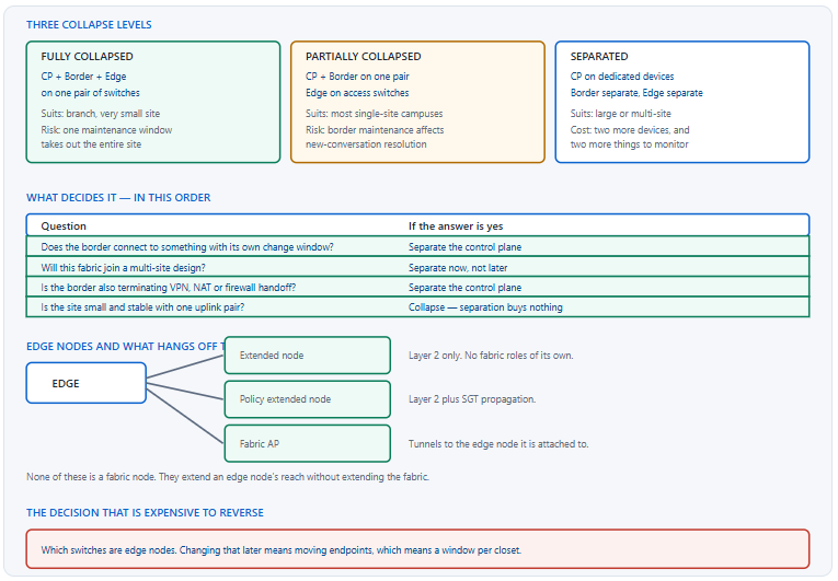
What Actually Decides Whether to Collapse or Separate Roles?
What is the deciding factor?
The change window, not the device count. Every role can be collapsed and every collapse is supported, so the question is what a single maintenance event takes out. A border node connected to a WAN circuit, terminating VPN, or handing off to a firewall has a change rate driven by things outside the campus, and putting the control plane on it means every one of those changes is also a control-plane change. That is the argument for separation, and it applies at any size.
A Deeper Dive into the Decision
What each collapse actually costs
Collapsing the control plane onto the border means border maintenance affects new-conversation resolution — existing traffic continues, new flows fail, and the impact grows as caches expire. Collapsing the edge role onto the same pair means the site's access layer is on the devices being maintained, which is a total outage rather than a partial one. Neither is wrong; both need to be understood before they are chosen rather than after.
! What roles is this device actually carrying?
SW1# show run | section router lisp
router lisp
 locator-set rloc_default
  IPv4-interface Loopback0 priority 10 weight 10
 !
 site site_uci              ! <- Map Server: this is a CP node
 !
 instance-id 4099
  service ipv4
   eid-table vrf CAMPUS
   map-cache 0.0.0.0/0 map-request   ! <- border behaviour
 !
 ipv4 map-server
 ipv4 map-resolver
!
! Three roles on one box is visible in one output.
The questions in order
| Question | Yes means | Why |
|---|---|---|
| Does the border connect to a WAN or provider circuit? | Separate the CP | Its change window is not yours |
| Does the border terminate VPN, NAT or a firewall handoff? | Separate the CP | More software, more change, more risk |
| Will this site join a multi-site fabric? | Separate now | Retrofitting is a project |
| Are there more than a handful of virtual networks? | Consider separating | Border config grows with VN count |
| Small, stable site with one uplink pair? | Collapse | Separation adds devices and no benefit |
Fabric in a box, and when it is right
A single pair of switches carrying every role is a legitimate design for a branch or a very small site, and it is considerably simpler to operate than the alternative. Its property is that the site has one failure domain — which is honest, because a two-switch site has one failure domain regardless of how the roles are labelled. The mistake is deploying it at a size where the site could have had more than one and did not.
Sizing against the right dimension
The instinct when sizing a fabric device is to look at throughput, and for edge nodes that is roughly right. For control plane nodes it is entirely wrong: they carry no user traffic at all, so throughput tells you nothing and the dimensions that bind are the endpoint count, the registration rate and the query rate. A control plane node on a modest platform serving a large fabric is a normal and correct outcome.
Border nodes are the opposite case, because they carry every packet leaving or entering the fabric and terminate the handoff for every virtual network. They are the one role where throughput sizing is the primary consideration, and they are also the role most often collapsed onto devices chosen for a different purpose. Checking that the border pair can carry the site's aggregate external traffic is a separate exercise from checking that it can hold the configuration.
! Border nodes carry real traffic - check both dimensions
BORDER1# show interfaces | include rate|Te1/0
BORDER1# show interfaces summary
!
! Control plane nodes carry none - check the other dimensions
CP1# show lisp site summary
CP1# show lisp instance-id 4099 ipv4 statistics | include Map-Request|Map-Register
CP1# show processes cpu sorted | include five seconds
Redundancy is per role, not per site
Two control plane nodes, two border nodes, and edge nodes that are individually non-redundant because each serves its own closet. That asymmetry is deliberate: losing an edge node affects the endpoints attached to it and nothing else, while losing the only control plane node affects every new conversation everywhere. Redundancy belongs where the blast radius is large, and applying it uniformly wastes hardware on the roles that do not need it.
! Confirm redundancy where it matters
EDGE1# show lisp instance-id 4099 ipv4 map-resolver
    Map-resolver         Uptime     State
    10.1.100.1           4d02h      up
    10.1.100.2           4d02h      up
! ^ Two. Anything less is a single point of failure.
!
EDGE1# show run | include use-petr
  ipv4 use-petr 10.1.1.1
  ipv4 use-petr 10.1.1.2
! ^ Two borders. Same requirement.
!
! Edge nodes are singly attached by design
EDGE1# show cdp neighbors | include Switch|Router
How Should Border Nodes Be Designed?
What are the choices?
Three that matter. How many border nodes — two is the minimum for redundancy and more than two is unusual in a single site. Which type each one is: internal for known prefixes, external for the default exit, anywhere for both. And what the handoff looks like, which is driven entirely by the virtual network count because each VN needs its own sub-interface and its own routing adjacency on every border.
A Deeper Dive into Border Design
Two anywhere borders is the common answer
In a single-site fabric with one connection to the rest of the world, both borders being anywhere borders is simple and correct: each advertises the default and the known prefixes, edge nodes use either, and losing one is a non-event. Splitting the internal and external roles onto different devices makes sense when the connections themselves are separate — a data centre link on one pair, an internet edge on another — and adds complexity when they are not.
! What an anywhere border advertises into the fabric
BORDER1# show lisp instance-id 4099 ipv4 database | include 0.0.0.0|10.5
0.0.0.0/0, locator-set rloc_default
  ! ^ the default - external border behaviour
10.5.0.0/16, locator-set rloc_default
  ! ^ a known prefix - internal border behaviour
!
! And what the edge nodes do with it
EDGE1# show ip route vrf CAMPUS 0.0.0.0
EDGE1# show ip route vrf CAMPUS 10.5.0.0
Handoff complexity scales with VN count
Every virtual network needs a sub-interface, an address, and a routing adjacency on every border, towards every device it hands off to. Three VNs and two borders and one upstream pair is twelve adjacencies; ten VNs is forty. This is the single most direct consequence of the segmentation design on the operational burden, and it is why the VN count is worth arguing about before any border is configured.
! One VN, one sub-interface, one peer. Multiply by everything.
interface TenGigabitEthernet1/0/1.3001
 description CAMPUS handoff to FUSION-1
 encapsulation dot1Q 3001
 vrf forwarding CAMPUS
 ip address 10.200.1.1 255.255.255.252
!
router bgp 65100
 address-family ipv4 vrf CAMPUS
  neighbor 10.200.1.2 remote-as 65000
  neighbor 10.200.1.2 activate
 exit-address-family
!
! Count what you actually have
BORDER1# show ip interface brief | count \.30
BORDER1# show bgp vpnv4 unicast all summary | count 65000
Where the fusion device sits
Virtual networks do not communicate inside the fabric, so anything that must cross between them does so on a device outside it. A firewall is the better choice for that role because the crossing point is exactly where inspection belongs and because a firewall's policy model is designed for exceptions. A router doing route leaking works and tends to accumulate an unauditable set of route-target entries over time.
| Fusion device | Crossing policy expressed as | Auditability | Suits |
|---|---|---|---|
| Firewall | Security rules between zones | Good — rules are the design | Most designs |
| Router with VRFs | Route targets and leaking | Poor — grows into exceptions | Simple shared-services only |
| No fusion device | Nothing crosses | Perfect | Truly independent VNs |
Keeping the SGT across the handoff
The group tag lives in the VXLAN header and has nowhere to go in an ordinary IP packet, so it has to be carried onward another way — inline tagging where the next device supports it, or a binding-propagation protocol where it does not. If neither is configured, policy stops at the border and everything beyond it sees untagged traffic, which is a legitimate design if intended and a surprise if not.
! Inline tagging to a capable neighbour
interface TenGigabitEthernet1/0/2
 cts manual
  policy static sgt 2 trusted
!
! Or propagate bindings out of band
cts sxp enable
cts sxp default source-ip 10.1.1.1
cts sxp connection peer 10.9.9.9 password default mode local speaker
!
! Confirm which one is actually in use
BORDER1# show cts interface TenGigabitEthernet1/0/2 | include Mode|SGT
BORDER1# show cts sxp connections brief
show switch shows multiple members in one stack rather than two independent devices; the edge nodes' use-petr list contains one address. Fix: two independent border devices with two separate addresses in the edge nodes' border list — the redundancy the fabric can actually use is at the role level, not the chassis level.How Many Edge Nodes, and What Belongs on Them?
What is an edge node and what is not?
An edge node is a switch that hosts the anycast gateway, registers endpoints, and encapsulates traffic — in practice, an access switch that supports the fabric feature set. Things attached to an edge node are not automatically edge nodes: an extended node is a Layer 2 switch hanging off one, a fabric access point tunnels to one, and neither has any fabric role of its own. Getting that distinction right determines what has to be upgraded and what does not.
A Deeper Dive into the Access Layer
Extended nodes, which extend reach not fabric
An extended node is a switch connected to an edge node over a trunk, carrying fabric subnets as ordinary VLANs. It is used where the access layer includes equipment that cannot be a fabric node — industrial switches in a plant, compact switches in a small space — and it works because the edge node it attaches to does all the fabric work on its behalf. A policy extended node adds the ability to carry group tags, which restores micro-segmentation to the ports behind it.
! The edge node's view of an extended node
EDGE1# show cdp neighbors GigabitEthernet1/0/47 detail | include Device|Platform
Device ID: EXT-SW-1
Platform: cisco IE-3400-8T2S
!
! The trunk carrying fabric subnets down to it
EDGE1# show interfaces trunk | include Gi1/0/47
Gi1/0/47    on    802.1q    trunking    1
!
! And confirm which VLANs are actually allowed
EDGE1# show interfaces GigabitEthernet1/0/47 trunk
Fabric wireless changes what an edge node carries
An access point in a fabric builds a tunnel to the edge node it is attached to, and wireless traffic is decapsulated there rather than travelling back to a controller. That means the edge node carries its wireless clients' traffic as well as its wired clients', and the endpoint count on it is the sum of both. It also means a wireless client gets the same anycast gateway, the same virtual network and the same policy enforcement as a wired one on the same switch.
! Wireless clients appear on the EDGE node, not the WLC
EDGE1# show access-tunnel summary
EDGE1# show wireless fabric summary
!
! And they register through the same control plane
EDGE1# show lisp instance-id 4099 ipv4 database | count /32
!
! Which means endpoint count is wired PLUS wireless
EDGE1# show device-tracking database | count REACHABLE
Why edge nodes are not made redundant
An access switch serves the ports plugged into it and nothing else, so its failure affects exactly those endpoints and no others. Making it redundant means dual-homing every host, which is impractical for the overwhelming majority of endpoints and unnecessary for almost all of them — a user whose switch has failed has a broken port, which is the same experience they would have had in any access design.
The exception worth designing for is the small number of endpoints that genuinely cannot tolerate that: a server closet, a critical appliance, a wireless controller. Those get dual attachment to two edge nodes and the fabric handles the rest, because a host registering from two edge nodes is a state the control plane already understands. Applying that treatment universally is expensive and applying it nowhere leaves the few genuinely critical endpoints exposed.
What limits endpoints per edge node
Three things, and which one binds depends on the platform: the endpoint tracking database, the mapping entries in hardware, and the policy bindings. A closet with two hundred wired ports and three access points serving a hundred wireless clients is carrying three hundred endpoints, not two hundred, and the wireless half is the part that tends to be forgotten in the sizing.
! Three counts that should be checked together
EDGE1# show device-tracking database | count REACHABLE
EDGE1# show lisp instance-id 4099 ipv4 database | count /32
EDGE1# show cts role-based sgt-map vrf CAMPUS all | count LOCAL
!
! And the hardware headroom behind them
EDGE1# show platform hardware fed switch active fwd-asic resource tcam utilization
The role that needs no configuration
An intermediate node is any switch in the underlay path that is not an edge, border or control plane node. It needs sufficient MTU and, where native multicast is used, PIM — and nothing else. It does not need to support the fabric feature set, does not need to be licensed for it, and does not need to be managed by the controller. This is worth knowing during hardware planning, because it means the core does not have to be replaced to deploy a fabric at the edge.
How Does a Design Change as the Fabric Grows?
What changes and what does not?
Adding edge nodes changes nothing structural — it is the operation the design is built for, and a new closet is a provisioning task. Adding virtual networks changes the border, which is why the VN list should be decided early. Adding sites changes everything about how the fabric connects to itself, and that is the transition worth designing for before it happens rather than during it.
A Deeper Dive into Growth
Adding an edge node
The cheapest operation in the design. The new switch is provisioned with the underlay, given the edge role, and starts registering endpoints; no other device changes. This is the property that makes the collapse decisions earlier in the design so consequential — everything that scales cleanly does so because the roles that do not scale cleanly were placed somewhere they are not being added to.
! After adding an edge node, three checks and nothing else
NEWEDGE# show lisp session
! ^ established to both control plane nodes
NEWEDGE# ping 10.1.1.9 source Loopback0 size 9000 df-bit
! ^ underlay reachability at full MTU
NEWEDGE# show cts environment-data | include status
! ^ has reached the policy server and downloaded the group list
!
! No other device requires a change.
Adding a virtual network
Considerably more expensive than it looks. Every border gains a sub-interface and a routing adjacency per upstream device, the fusion device gains a routing context and whatever leaking policy the new VN needs, and both grow the configuration that has to be maintained and replicated at every future site. The cost is entirely at the border, which is why it is invisible when the VN is being requested and obvious when it is being implemented.
! What adding one VN touches - per border, per upstream device
!
! 1. The sub-interface
interface TenGigabitEthernet1/0/1.3004
 encapsulation dot1Q 3004
 vrf forwarding NEWVN
 ip address 10.200.1.13 255.255.255.252
!
! 2. The routing adjacency
router bgp 65100
 address-family ipv4 vrf NEWVN
  neighbor 10.200.1.14 remote-as 65000
  neighbor 10.200.1.14 activate
 exit-address-family
!
! 3. The fusion device's matching context and leaking policy
! 4. Repeat for the second border.
! 5. Repeat all of it at every future site.
Adding a site
Two ways to connect fabrics, with different properties. Handing off at each border into an ordinary routed network preserves the virtual networks as separate routing contexts and requires the group tag to be carried separately. Keeping traffic encapsulated between sites preserves both natively and requires a transit control plane node and a transit network able to carry the encapsulation. The second is cleaner and constrains what the network between sites can be.
| Property | IP transit | Fabric transit |
|---|---|---|
| Virtual network preserved | As separate routing contexts per hop | Natively |
| Group tag preserved | Only if carried separately | Natively, in the header |
| Requirement on the network between | Any IP connectivity | Must carry the encapsulation and MTU |
| Additional role needed | None | Transit control plane node |
| Configuration per site | A handoff per VN | Registration with the transit control plane |
| Suits | Existing WAN, third-party circuits | Owned transit between campuses |
Designing the first site for the second one
Most of the decisions that make a second site expensive are made when there is only one. A generously sized loopback pool means a new site draws from the same summary. A control plane separated from the border means the transit control plane role has somewhere sensible to live. A restrained VN list means the handoff configuration replicated at the new site is short. None of these costs anything at the first site and all of them are awkward to retrofit.
! Decisions at site one that pay off at site two
!
! Loopback pool sized for growth, one summary
BORDER1# show ip route isis | include 10.1.1.0/24
! ^ one prefix covering every fabric node, at every site
!
! Control plane on its own devices
CP1# show run | include ^hostname|map-server
!
! And a VN list short enough to replicate
BORDER1# show vrf | count :
Which Role Decisions Are Expensive to Reverse?
What should be got right first?
Four. Which switches are edge nodes, because changing that means moving endpoints. Whether the control plane is separated, because moving it on a live fabric is a migration. The virtual network list, because consolidating VNs means renumbering hosts. And the loopback addressing plan, because a second summary is a permanent complication in every routing table and every document.
A Deeper Dive into the Irreversible Decisions
Which switches are edge nodes
Moving the control plane later
show lisp instance-id <id> ipv4 map-resolver across the fleet shows a mix of old and new addresses during the change. Fix: run the new nodes alongside the old ones so edge nodes register with all four during the transition, then remove the old pair — and accept that this is a project rather than a change.The addressing plan
A design review checklist
! Questions worth answering before the first switch is provisioned
!
! 1. Which devices carry which roles, and why?
! 2. What does one maintenance window on each take out?
! 3. How many VNs, and does each need a separate routing table?
! 4. How many border handoff adjacencies does that produce?
! 5. Is the loopback pool sized for two more sites?
! 6. Which access switches are NOT going to be edge nodes, and why?
! 7. Where does the group tag stop, and is that intended?
! 8. What is the fusion device, and who owns its policy?
!
! Every one of these is cheap now and expensive later.
Reversing a decision that has to be reversed
Sometimes the early decision was wrong and has to change anyway. The approach that works in every case is the same: run the new arrangement alongside the old one rather than swapping, move devices across in batches small enough to verify, and remove the old arrangement only when nothing references it. That is slower than a cutover and it is the difference between a series of small windows and one large one that either works or does not.
The prerequisite is that the fabric supports both arrangements simultaneously, which it generally does — four control plane nodes rather than two, a second border pair alongside the first, an additional loopback range advertised alongside the original. Each of those is a supported transient state, and treating it as the migration path rather than as an anomaly is what makes the reversal manageable.
What to document, and where
Role assignment is invisible from most command output — a device carrying three roles looks like a device with a long configuration. A short table naming each device and its roles, kept where the operations team reads it rather than in a design document, is what makes an incident response start in the right place. Interface descriptions naming the role a link serves do the same job at the point where someone is about to change something.
Blueprint framing
The CCIE Enterprise Infrastructure v1.1 blueprint covers SD-Access design within the software-defined infrastructure domain, and role questions tend to be about consequence rather than syntax: what a border node does, what happens when a control plane node fails, which devices need the fabric feature set and which do not. Being able to reason about failure domains rather than recite a role list is what those questions are testing.
Conclusion
Role assignment in a fabric is a failure-domain exercise wearing a device-count costume. Every collapse is supported, so support is not the criterion; what matters is what a single change or a single failure takes out, and that is determined by whose operational calendar drives each device. A border connected to a WAN circuit has a change rate set by someone else, which is the strongest single argument for keeping the control plane off it regardless of site size.
Border design is dominated by one number that comes from somewhere else entirely. Handoff complexity is virtual networks multiplied by borders multiplied by upstream devices, so the segmentation decision — made by people thinking about security policy — determines the border's operational burden. Working out the border configuration on paper for a proposed VN list, before anything is provisioned, tends to shorten the list on its own.
Growth exposes the early decisions. Adding an edge node touches one device and is the operation the design is built for. Adding a virtual network touches every border. Adding a site exposes whether the control plane was separated, whether the loopback pool was sized generously, and whether the VN list is short enough to replicate. All three of those are free at the first site and cost a project at the second, which is the argument for making them deliberately rather than by default.
External Links
- Cisco Design Zone — Campus Wired and Wireless Design Guides
- Cisco — Software-Defined Access Configuration Guide, Catalyst 9300
- RFC 9300 — The Locator/ID Separation Protocol (LISP)
- RFC 7348 — Virtual eXtensible Local Area Network (VXLAN)
- RFC 4364 — BGP/MPLS IP Virtual Private Networks (VPNs)
- Cisco TrustSec Configuration Guide
- Cisco Learning Network — CCIE Enterprise Infrastructure
Reference Notes
- Cisco documentation describes the SD-Access fabric roles: edge node, control plane node, border node, intermediate node, and fabric-enabled wireless LAN controller.
- Cisco documentation states that fabric roles may be collocated on the same physical device, including designs where the control plane and border roles share a platform.
- Cisco documentation distinguishes internal, external and anywhere border nodes by whether they advertise known prefixes, a default route, or both into the fabric.
- Cisco documentation describes the border handoff as a VRF-lite configuration with an 802.1Q sub-interface and a routing adjacency per virtual network.
- Cisco documentation describes extended nodes as Layer 2 switches connected to a fabric edge node over a trunk, without themselves holding a fabric role.
- Cisco documentation describes policy extended nodes, which additionally support scalable group tag propagation for the endpoints connected to them.
- Cisco documentation describes fabric access points as building a tunnel to the fabric edge node they attach to, so that wireless traffic is decapsulated at the edge node.
- Cisco documentation states that intermediate nodes require only appropriate MTU and, where native multicast is used, PIM, and need no fabric-specific configuration.
- Cisco documentation describes SD-Access transit, which requires a transit control plane node and preserves virtual network and group tag information between fabric sites.
- RFC 4364 defines the VRF and route target mechanisms used by fusion devices to leak selected prefixes between virtual networks outside the fabric.
- Cisco TrustSec documentation describes inline tagging and binding propagation as the two mechanisms for carrying group tags beyond a fabric border.
- The CCIE Enterprise Infrastructure v1.1 unified exam topics include SD-Access design within the software-defined infrastructure domain.