

DMVPN is four technologies working together and the difficulty is almost never in any one of them. A multipoint GRE interface provides an overlay that can reach many destinations from one interface. NHRP provides the mapping from an overlay address to the real address underneath. A routing protocol distributes prefixes across the overlay. IPsec, optionally, protects it. Each is straightforward; the interactions are where the phases come from and where the failures live.
Phase 3 exists because Phase 2 forced an unpleasant trade. To let spokes build direct tunnels, Phase 2 required the hub to preserve the original next hop and therefore to advertise every spoke's prefixes individually — which meant no summarisation, a full routing table on every spoke, and a design that stopped scaling somewhere in the low hundreds. Phase 3 breaks that dependency by letting the routing table say "via the hub" while the forwarding table says something else entirely.
This article covers what actually differs between the three phases, how a spoke-to-spoke tunnel is built by redirect and resolution, how the routing protocol should be configured now that summarisation is allowed again, how to secure and scale the cloud, and the failure catalogue — the cases where everything looks healthy and every packet still goes through the hub.
What Do the Three DMVPN Phases Actually Differ On?
What is the distinction?
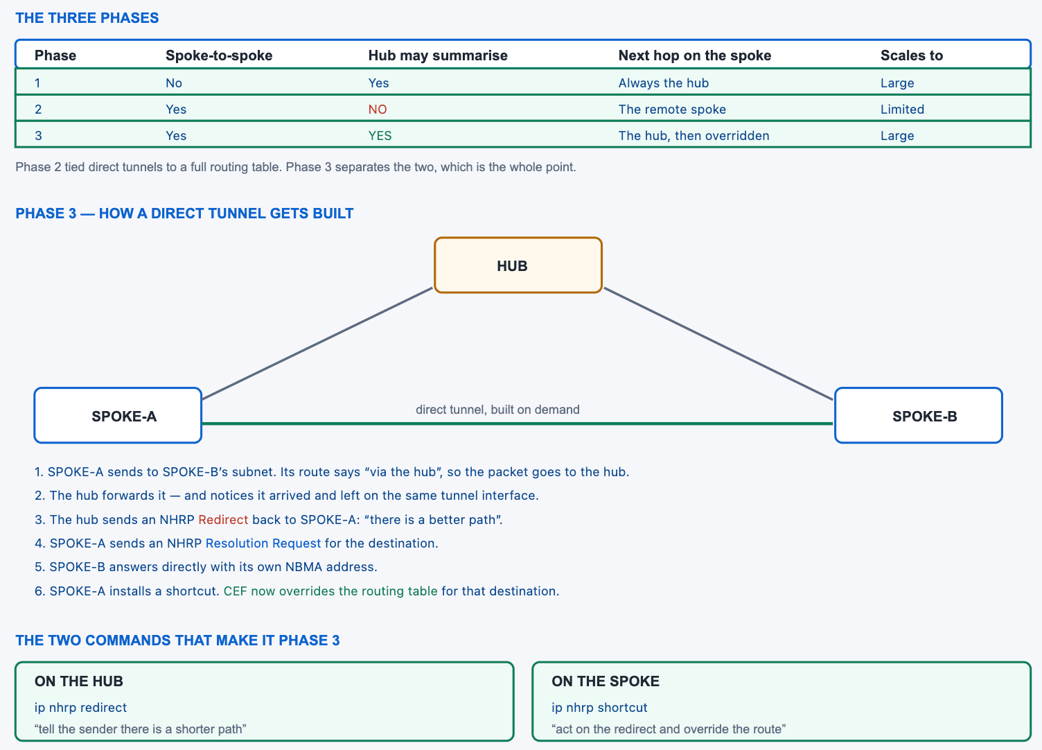
Two things: whether spokes can build direct tunnels to each other, and whether the hub is allowed to summarise. Phase 1 has no direct tunnels and full freedom to summarise. Phase 2 has direct tunnels and no summarisation, because the spoke needs the remote spoke's tunnel address as the next hop and a summary destroys it. Phase 3 has both, because the direct tunnel is established by a forwarding-plane override rather than by what the routing table says.
A Deeper Dive into the Phases
What Phase 2 actually costs
For a spoke to build a tunnel to another spoke, its routing table must contain the destination prefix with the remote spoke's tunnel address as the next hop. That requires the hub to advertise every spoke prefix individually and to refrain from rewriting the next hop — so no summary, no default route, and every spoke carrying every other spoke's prefixes. At fifty spokes that is inconvenient; at five hundred it is the reason the design does not work.
! Phase 2 hub - the constraints that limit it
interface Tunnel0
 ip address 10.0.0.1 255.255.255.0
 no ip split-horizon eigrp 100
 no ip next-hop-self eigrp 100
 ! ^ both required, and both prevent summarisation
 tunnel mode gre multipoint
!
! The result on a spoke: every other spoke's prefix, individually
SPOKE-A# show ip route eigrp | count via 10.0.0.
Number of lines which match regexp = 247
! ^ 247 prefixes so that direct tunnels can be built.
Why Phase 1 still has a place
Phase 1 is often described as obsolete and is not. A design where every branch talks to a data centre and branches have no reason to talk to each other gains nothing from direct tunnels, and Phase 1 delivers that with a simpler configuration, a point-to-point tunnel per spoke if preferred, and no NHRP resolution behaviour to reason about. Where the traffic pattern is genuinely hub-and-spoke, the extra machinery is complexity without benefit.
The case for Phase 3 is a traffic pattern with meaningful branch-to-branch volume — voice between offices, file access between sites, or an application deployed regionally rather than centrally. That is common enough to be the default assumption, and it is worth confirming rather than assuming, because the answer determines whether the resolution behaviour needs to be understood and monitored at all.
What Phase 3 changes
The spoke's routing table can now say anything — a summary, or just a default route pointing at the hub. Traffic starts on the hub path, the hub notices it is hairpinning and issues a redirect, and the spoke resolves the real destination and installs an override. The routing table is never modified; the forwarding table is. That separation is what allows a spoke to hold three routes and still talk directly to four hundred peers.
! Phase 3 hub - summarise freely
interface Tunnel0
 ip address 10.0.0.1 255.255.255.0
 ip nhrp redirect
 ip summary-address eigrp 100 10.0.0.0 255.0.0.0
 tunnel mode gre multipoint
!
! Phase 3 spoke - act on redirects
interface Tunnel0
 ip address 10.0.0.11 255.255.255.0
 ip nhrp shortcut
 tunnel mode gre multipoint
!
! The result on a spoke: almost nothing in the table
SPOKE-A# show ip route eigrp
D     10.0.0.0/8 [90/26880000] via 10.0.0.1, 00:41:12, Tunnel0
! ^ One summary. Direct tunnels still work.
The three compared properly
| Property | Phase 1 | Phase 2 | Phase 3 |
|---|---|---|---|
| Spoke tunnel interface | p2p GRE or mGRE | mGRE | mGRE |
| Direct spoke-to-spoke | No | Yes | Yes |
| Hub summarisation | Yes | No | Yes |
| Next hop preserved by hub | Irrelevant | Required | Not required |
| Trigger for the direct tunnel | — | Routing table next hop | NHRP redirect |
| Key commands | — | no ip next-hop-self |
ip nhrp redirect / shortcut |
| Practical scale | Large | Limited by table size | Large |
Building the tunnel interface
The tunnel itself is the same in every phase apart from the two Phase 3 commands. A multipoint GRE mode, a source, a network identifier that groups the cloud, a key where several clouds share a source, and the multicast mapping that lets routing protocol hellos traverse it. Nothing here is subtle, and getting the network identifier or the key mismatched produces a tunnel that comes up and registers nothing.
! Hub, complete
interface Tunnel0
 ip address 10.0.0.1 255.255.255.0
 ip mtu 1400
 ip tcp adjust-mss 1360
 ip nhrp authentication DMVPNKEY
 ip nhrp map multicast dynamic
 ip nhrp network-id 100
 ip nhrp holdtime 600
 ip nhrp redirect
 tunnel source GigabitEthernet0/0
 tunnel mode gre multipoint
 tunnel key 100
 tunnel protection ipsec profile DMVPN-PROFILE
! Spoke, complete
interface Tunnel0
 ip address 10.0.0.11 255.255.255.0
 ip mtu 1400
 ip tcp adjust-mss 1360
 ip nhrp authentication DMVPNKEY
 ip nhrp network-id 100
 ip nhrp holdtime 600
 ip nhrp nhs 10.0.0.1 nbma 203.0.113.1 multicast
 ! ^ modern single-line form: server, its real address, and
 !   the multicast mapping, all at once
 ip nhrp shortcut
 tunnel source GigabitEthernet0/0
 tunnel mode gre multipoint
 tunnel key 100
 tunnel protection ipsec profile DMVPN-PROFILE
The NHRP messages worth recognising
NHRP is a small protocol and knowing its five message types makes the debug output readable rather than opaque. Registration is a spoke telling the server where it is. Resolution request and reply are the lookup that produces a direct tunnel. Purge invalidates an entry that is no longer valid. And the traffic indication — the redirect — is what makes Phase 3 different from Phase 2.
| Message | Sent by | Means | Seen when |
|---|---|---|---|
| Registration Request | Spoke | “My tunnel address maps to this real address” | At startup and every holdtime/3 |
| Registration Reply | Hub | “Accepted” | Immediately after |
| Resolution Request | Spoke | “Which real address owns this destination?” | After a redirect |
| Resolution Reply | Destination spoke | “I do, at this address” | Sent directly to the requester |
| Traffic Indication | Hub | “There is a shorter path than through me” | Phase 3 only |
| Purge Request | Either | “Discard the entry you hold” | On a mapping change |
Verifying the cloud is formed
! The single most useful DMVPN command
HUB# show dmvpn
Interface: Tunnel0, IPv4 NHRP Details
Type:Hub, NHRP Peers:3,
 # Ent  Peer NBMA Addr Peer Tunnel Add State  UpDn Tm Attrb
 ----- --------------- --------------- ----- -------- -----
     1    203.0.113.11        10.0.0.11    UP 00:41:02     D
     1    203.0.113.12        10.0.0.12    UP 00:40:55     D
     1    203.0.113.13        10.0.0.13    UP 00:38:19     D
! Attrb D = dynamically registered. On a spoke, the hub
! entry shows S for static.
!
HUB# show dmvpn detail
HUB# show ip nhrp brief
dmvpn phase 3 command. A cloud is Phase 3 because the hub has ip nhrp redirect and the spokes have ip nhrp shortcut, and Phase 2 because they do not. A cloud where half the spokes have shortcut configured is genuinely half of each, which is a state worth checking for rather than assuming.How Does NHRP Build a Spoke-to-Spoke Tunnel in Phase 3?
What is the sequence?
Six steps. The first packet follows the routing table to the hub. The hub forwards it and observes that it arrived and departed on the same tunnel interface, which means the path is not optimal. The hub sends a redirect to the sender. The sender issues a resolution request for the destination. The destination spoke answers directly with its own real address. The sender installs a shortcut entry, and the forwarding table now bypasses the hub for that destination.
A Deeper Dive into the Exchange
The redirect is triggered by hairpinning
The hub does not track which spokes should talk to each other. It simply notices that a packet came in on the tunnel and went back out on the same tunnel, which is the definition of a suboptimal path in this topology, and issues a redirect on that basis. This is why the mechanism needs no configuration beyond one command and why it works for any traffic pattern without being told about it in advance.
! Watch the redirect being generated on the hub
HUB# debug nhrp packet
NHRP: Send Traffic Indication via Tunnel0 vrf global(0x0),
      packet size: 96
NHRP:    src: 10.0.0.1, dst: 10.0.0.11
NHRP:    (F) afn: AF_IP(1), type: IP(800), hop: 255
NHRP:    (M) traffic code: redirect(0)
! ^ The hub is telling SPOKE-A to look for a better path.
!
HUB# undebug all
HUB# show ip nhrp traffic | include Indication|Resolution
Resolution goes to the destination, not the hub
The resolution request is forwarded across the cloud to whichever spoke owns the destination, and that spoke replies directly to the requester with its own real address. The hub relays the request and takes no part in the reply, which is what makes the resulting tunnel genuinely direct rather than something the hub brokered and remains in the middle of.
! On the requesting spoke, after traffic starts
SPOKE-A# show ip nhrp
10.0.0.12/32 via 10.0.0.12
   Tunnel0 created 00:00:14, expire 00:09:46
   Type: dynamic, Flags: router used nhop
   NBMA address: 203.0.113.12
!
10.10.12.0/24 via 10.0.0.12
   Tunnel0 created 00:00:14, expire 00:09:46
   Type: dynamic, Flags: router rib
   NBMA address: 203.0.113.12
! ^ Two entries: the peer itself, and the destination
!   network reachable through it. The second is the shortcut.
The forwarding override
The routing table is not modified. It still says the destination is reachable via the hub, and it will say that forever. What changed is the forwarding entry, where NHRP has installed an override pointing at the remote spoke. Reading the routing table during troubleshooting therefore tells you nothing about whether a direct tunnel is in use, which is the single most misleading thing about Phase 3.
! The route still points at the hub - and always will
SPOKE-A# show ip route 10.10.12.5
Routing entry for 10.0.0.0/8
  Known via "eigrp 100", distance 90, metric 26880000
  * 10.0.0.1, from 10.0.0.1, 00:44:02 ago, via Tunnel0
! ^ via the HUB. Looks like traffic goes through the hub.
!
! The forwarding table tells the truth
SPOKE-A# show ip cef 10.10.12.5
10.10.12.0/24
  nexthop 10.0.0.12 Tunnel0
! ^ Directly to SPOKE-B. This is the override.
!
SPOKE-A# show ip cef exact-route 10.10.11.5 10.10.12.5
Confirming the tunnel exists rather than assuming
! On the spoke, a direct peer appears in the DMVPN table
SPOKE-A# show dmvpn
Interface: Tunnel0, IPv4 NHRP Details
Type:Spoke, NHRP Peers:2,
 # Ent  Peer NBMA Addr Peer Tunnel Add State  UpDn Tm Attrb
 ----- --------------- --------------- ----- -------- -----
     1     203.0.113.1        10.0.0.1    UP 00:44:19     S
     1    203.0.113.12       10.0.0.12    UP 00:00:31     DT1
! S   = the static hub entry
! DT1 = a dynamic entry created by a resolution - the shortcut
!
! And the traffic counters prove it is being used
SPOKE-A# show interfaces Tunnel0 | include packets output
SPOKE-A# show ip nhrp traffic | include Resolution
Reading the cache flags
The NHRP cache annotates each entry with flags that say where it came from and what it is for, and they answer most questions about a shortcut faster than any other output. An entry flagged as used carries traffic; one flagged for the routing table is a network prefix rather than a peer; a local entry is this router's own registration. An incomplete entry is a resolution that was sent and not answered, which is a specific and useful thing to know.
The distinction between the peer entry and the prefix entry matters when reading the output. A working shortcut produces both: one mapping the remote spoke's tunnel address to its real address, and one mapping the destination network to that spoke. Seeing only the first means the peer is known and the prefix is not, which points at the resolution rather than at the tunnel.
! The flags, and what each one tells you
SPOKE-A# show ip nhrp detail
!
!  used       - traffic is flowing through this entry
!  nhop       - this is a next-hop (peer) entry
!  rib        - this entry corresponds to a routing prefix
!  local      - this router's own registration
!  router     - the peer is a router, not a host
!  (no reply) - resolution sent, nothing came back
!
! Count what is actually in the cache
SPOKE-A# show ip nhrp brief | count via
SPOKE-A# show ip nhrp summary
Ageing and re-resolution
Shortcut entries expire on the NHRP holdtime, and traffic that is still flowing causes them to be refreshed before they do. A conversation that stops leaves the entry to age out and the next conversation starts on the hub path again — one round trip through the hub, then a redirect, then a direct tunnel. That is intended behaviour and it means a brief hub hairpin at the start of a flow is normal rather than a fault.
! Holdtime governs how long a shortcut survives idle
interface Tunnel0
 ip nhrp holdtime 600
! ^ Default is 7200 s. Lower values free stale entries
!   sooner and cost more re-resolution.
!
! Registration happens at one third of the holdtime
SPOKE-A# show ip nhrp nhs detail
Legend: E=Expecting replies, R=Responding
Tunnel0:
  10.0.0.1  RE  priority = 0 cluster = 0  req-sent 122  req-failed 0  repl-recv 122
!
! Clear one entry to force a fresh resolution
SPOKE-A# clear ip nhrp
show dmvpn for the peer entry and show ip cef for the override are the two commands that distinguish them, and neither takes more than a few seconds.show ip route equally uninformative whether the direct tunnel exists or not.How Should the Routing Protocol Be Configured on a Phase 3 Hub?
What changes now that summarisation is allowed?
Nearly everything that Phase 2 forced becomes optional. The hub can advertise a summary or a default and rewrite the next hop to itself, because the next hop no longer determines whether direct tunnels form. Split horizon still matters for whether spokes learn about each other at all, but with a summary in play they do not need to. The result is a much smaller and much more conventional routing configuration.
A Deeper Dive into Routing
EIGRP, which is the common choice
EIGRP over DMVPN is straightforward in Phase 3: summarise on the tunnel interface, leave next-hop-self at its default, and the spokes hold one or two prefixes. The hub still needs enough neighbour capacity for every spoke, and the timers deserve attention because a large cloud with default timers produces a substantial hello and query load on one router.
! EIGRP hub - Phase 3, summarised
router eigrp CORP
 address-family ipv4 unicast autonomous-system 100
  af-interface Tunnel0
   summary-address 10.0.0.0 255.0.0.0
   hello-interval 20
   hold-time 60
   no split-horizon
   authentication mode hmac-sha-256 SharedSecret
  exit-af-interface
  network 10.0.0.0 0.255.255.255
  eigrp router-id 10.255.255.1
  eigrp stub-site 100:1
 exit-address-family
!
! Verify the summary is what spokes receive
SPOKE-A# show ip route eigrp
SPOKE-A# show ip eigrp neighbors
Stub configuration on the spokes
A spoke has one path out and no transit role, which makes it a textbook stub. Marking it as one stops the hub from sending queries to it, which is the single largest reduction in control-plane load available in a large cloud and removes an entire class of stuck-in-active problems.
! Spoke - a stub, because it transits nothing
router eigrp CORP
 address-family ipv4 unicast autonomous-system 100
  af-interface Tunnel0
   hello-interval 20
   hold-time 60
   authentication mode hmac-sha-256 SharedSecret
  exit-af-interface
  network 10.0.0.0 0.255.255.255
  network 10.10.11.0 0.0.0.255
  eigrp router-id 10.255.255.11
  eigrp stub connected summary
 exit-address-family
!
! Confirm the hub sees it as a stub
HUB# show ip eigrp neighbors detail | include Stub|Peer
   Stub Peer Advertising ( CONNECTED SUMMARY ) Routes
OSPF, and the network type question
OSPF over DMVPN works and needs the network type set deliberately, because the default for a tunnel interface produces neighbour relationships that do not match the topology. Point-to-multipoint is the honest choice for a hub-and-spoke overlay: it advertises host routes for each neighbour, requires no designated router election, and does not care that spokes cannot reach each other directly at the time adjacency forms.
! OSPF over DMVPN - set the type explicitly on both ends
interface Tunnel0
 ip ospf network point-to-multipoint
 ip ospf 1 area 0
 ip ospf hello-interval 10
 ip ospf dead-interval 40
!
! The alternative, where the hub must be DR
!   hub:   ip ospf network broadcast / ip ospf priority 255
!   spoke: ip ospf network broadcast / ip ospf priority 0
!
SPOKE-A# show ip ospf interface Tunnel0 | include Network Type|State
SPOKE-A# show ip ospf neighbor
Two hubs and how the spoke chooses
With two hubs the routing protocol decides which is preferred, and the usual approach is to make one clearly better rather than to load-share. Equal-cost paths across two hubs sound attractive and produce a design where a given flow's path depends on hashing, which complicates both troubleshooting and any per-flow policy. A deterministic primary with a clean failover is easier to operate and loses very little.
The mechanism is whatever the protocol offers: a higher delay or a worse metric on the backup hub's tunnel, a longer AS path, or a local preference. What matters is that the choice is expressed once on the hub side rather than configured on every spoke, so that adding a spoke inherits the intended preference automatically.
! Make the backup hub less attractive, from the hub side
! EIGRP: worsen the delay on the backup hub's tunnel
router eigrp CORP
 address-family ipv4 unicast autonomous-system 100
  af-interface Tunnel0
   delay 2000
  exit-af-interface
 exit-address-family
!
! BGP: set local preference outbound to the spokes
route-map BACKUP-HUB permit 10
 set local-preference 90
!
! Confirm the spoke prefers the primary
SPOKE-A# show ip route 10.0.0.0
SPOKE-A# show ip eigrp topology 10.0.0.0/8
Which protocol for which size
| Protocol | Suits | Watch | Phase 3 note |
|---|---|---|---|
| EIGRP | Most enterprise clouds | Query scope; use stub on spokes | Summarise on the tunnel, leave next-hop-self alone |
| OSPF | Small to medium clouds | Network type must be set | All spokes in one area; the hub is the ABR |
| BGP | Very large clouds | Configuration volume without dynamic peers | Use a listen range so spokes need no hub-side config |
| Static / default only | Simple spokes | No failover between hubs | Works, since Phase 3 only needs a path to the hub |
BGP with dynamic neighbours
At large scale the appeal of BGP is that a listen range lets the hub accept sessions from any spoke in a subnet without a configuration line per spoke — which means adding the four hundredth spoke requires no change on the hub at all. That is a meaningful operational difference from EIGRP or OSPF, both of which need the hub to have capacity but not per-spoke configuration either; the real BGP advantage is policy control and update packing.
! Hub accepts sessions from any spoke in the tunnel subnet
router bgp 65000
 bgp listen range 10.0.0.0/24 peer-group SPOKES
 neighbor SPOKES peer-group
 neighbor SPOKES remote-as 65000
 neighbor SPOKES password 7 08351F1B
 !
 address-family ipv4 unicast
  neighbor SPOKES activate
  neighbor SPOKES route-reflector-client
  neighbor SPOKES default-originate
  neighbor SPOKES prefix-list FROM-SPOKE in
 exit-address-family
!
HUB# show bgp ipv4 unicast summary | include 10.0.0.
HUB# show bgp listen range 10.0.0.0/24
ip nhrp redirect and ip nhrp shortcut, and the Phase 2 routing constraints — no ip next-hop-self and the absence of a summary — were never removed. Nothing breaks, so nothing prompts the cleanup. Confirm: show ip route eigrp | count on a spoke returns far more prefixes than the design needs. Fix: add the summary on the tunnel interface and remove the next-hop-self exception; the direct tunnels continue to work because they no longer depend on either.How Do I Secure and Scale a Phase 3 Cloud?
What are the components?
IPsec protection applied as a profile to the tunnel rather than as a crypto map, NHRP authentication so that a device cannot register into the cloud without the shared value, routing protocol authentication, and a second hub for redundancy. Scaling adds two more considerations: the MTU arithmetic, which is not optional once encryption is in play, and per-tunnel policy where spoke bandwidths differ.
A Deeper Dive into Protection and Scale
IPsec as a tunnel profile
Tunnel protection applies the IPsec profile directly to the tunnel interface, which is considerably simpler than the crypto map approach it replaced and is what makes a single mGRE interface able to protect sessions to many peers. The shared keyword matters when one physical source serves several tunnel interfaces, and omitting it in that situation produces a security association conflict that is awkward to diagnose.
! Modern IKEv2 protection, applied to the tunnel
crypto ikev2 proposal DMVPN-PROP
 encryption aes-cbc-256
 integrity sha256
 group 14
!
crypto ikev2 policy DMVPN-POL
 proposal DMVPN-PROP
!
crypto ikev2 keyring DMVPN-KR
 peer ANY
  address 0.0.0.0 0.0.0.0
  pre-shared-key SharedSecretValue
!
crypto ikev2 profile DMVPN-IKE
 match identity remote address 0.0.0.0
 authentication local pre-share
 authentication remote pre-share
 keyring local DMVPN-KR
 dpd 30 5 on-demand
!
crypto ipsec transform-set DMVPN-TS esp-aes 256 esp-sha256-hmac
 mode transport
!
crypto ipsec profile DMVPN-PROFILE
 set transform-set DMVPN-TS
 set ikev2-profile DMVPN-IKE
!
interface Tunnel0
 tunnel protection ipsec profile DMVPN-PROFILE shared
The MTU arithmetic
GRE adds 24 bytes and IPsec in transport mode adds several dozen more depending on the transform. The widely used values of a 1400-byte tunnel MTU and a 1360-byte TCP adjustment leave headroom for both and are worth applying as a default rather than calculating each time. Omitting them produces the familiar symptom of small packets working and large transfers hanging, which is diagnosed as an application problem far more often than as an MTU one.
! Both lines, on hub and every spoke
interface Tunnel0
 ip mtu 1400
 ip tcp adjust-mss 1360
!
! Test the real path MTU rather than assuming
SPOKE-A# ping 10.10.12.5 size 1400 df-bit
!!!!!
SPOKE-A# ping 10.10.12.5 size 1500 df-bit
.....
! ^ A clean boundary here confirms the values are right.
!
SPOKE-A# show interfaces Tunnel0 | include MTU
Two hubs, and what a spoke does with them
A spoke can register with several next hop servers, and the priority value decides which it prefers. Both hubs carry the same cloud identifier and key, both accept registrations, and the routing protocol decides which path is used in steady state. Spoke-to-spoke tunnels are unaffected by which hub is active, because once a shortcut exists neither hub is in the path.
! A spoke registering with both hubs
interface Tunnel0
 ip nhrp nhs 10.0.0.1 nbma 203.0.113.1 multicast
 ip nhrp nhs 10.0.0.2 nbma 198.51.100.1 multicast
 ip nhrp nhs cluster 0 max-connections 2
!
! Confirm both are responding
SPOKE-A# show ip nhrp nhs detail
Legend: E=Expecting replies, R=Responding
Tunnel0:
  10.0.0.1  RE  priority = 0 cluster = 0  req-sent 142 req-failed 0 repl-recv 142
  10.0.0.2  RE  priority = 0 cluster = 0  req-sent 142 req-failed 0 repl-recv 142
! ^ Both must show R. E without R means registrations are
!   being sent and not answered.
Separating the underlay from the overlay
A front-door VRF puts the tunnel source interface and the underlay routing into their own table, separate from the overlay traffic the tunnel carries. The practical benefit is that the internet-facing routing — a default route to a provider, a public address — cannot leak into the enterprise table, and the enterprise table cannot accidentally provide a path that bypasses the tunnel. On a branch router with one internet circuit that separation is worth having.
It also makes dual-provider designs tractable, because each provider's routing lives in its own table and the tunnel source can be selected per cloud. The configuration is small: a VRF for the outside, the physical interface placed in it, and the tunnel told which VRF to use for its source lookups.
! Front-door VRF: underlay in its own table
vrf definition INTERNET
 address-family ipv4
 exit-address-family
!
interface GigabitEthernet0/0
 vrf forwarding INTERNET
 ip address dhcp
!
ip route vrf INTERNET 0.0.0.0 0.0.0.0 dhcp
!
interface Tunnel0
 tunnel source GigabitEthernet0/0
 tunnel vrf INTERNET
 ! ^ the tunnel's OUTER lookup happens in INTERNET;
 !   the traffic it carries stays in the global table
!
! Verify each half separately
SPOKE-A# show ip route vrf INTERNET 0.0.0.0
SPOKE-A# show ip route 10.0.0.0
Per-tunnel policy where spokes differ
A hub with a ten-gigabit uplink sending to a spoke on a fifty-megabit circuit will overrun it, and the hub has no per-spoke visibility by default because all the spokes share one tunnel interface. NHRP groups solve this: the spoke advertises which group it belongs to, and the hub applies the matching shaping policy to traffic destined for that spoke specifically.
! On the spoke - declare which bandwidth group it belongs to
interface Tunnel0
 ip nhrp group SPOKE-50M
!
! On the hub - map the group to a shaping policy
interface Tunnel0
 ip nhrp map group SPOKE-50M service-policy output SHAPE-50M
 ip nhrp map group SPOKE-100M service-policy output SHAPE-100M
!
policy-map SHAPE-50M
 class class-default
  shape average 50000000
  service-policy CHILD-QOS
!
! Verify the policy attached to the right peer
HUB# show policy-map multipoint
HUB# show dmvpn detail | include Group|NHRP group
Which DMVPN Failures Leave Traffic on the Hub?
What are the failures worth memorising?
Five. Redirect configured and shortcut missing, or the reverse. A mismatched network identifier or tunnel key, which prevents registration entirely. Spokes behind address translation that cannot reach each other's real addresses. An MTU shortfall that makes the direct tunnel form and carry nothing useful. And a routing configuration where the spoke has no route at all for the destination, so no packet is ever sent to the hub and no redirect is ever triggered.
A Deeper Dive into the Failure Catalogue
Half a Phase 3 configuration
ip nhrp shortcut is not configured on the spoke's tunnel interface. Nothing errors, because a redirect that is ignored is not a failure condition. Confirm: show dmvpn on the spoke lists only the hub; show ip nhrp traffic on the spoke shows redirects received and no resolution requests sent. Fix: add ip nhrp shortcut to the spoke, and audit the whole cloud rather than one spoke — this is nearly always missing on more than one.Registration that never happens
show dmvpn on the hub lists no peers at all. The spoke appears to be sending and nothing is arriving. Cause: the NHRP network identifier groups a cloud and the tunnel key distinguishes overlapping clouds on one source address. A mismatch in either causes the receiver to discard the registration silently, because as far as it is concerned the packet belongs to a different cloud. Confirm: compare ip nhrp network-id and tunnel key on both ends; show ip nhrp traffic on the hub shows no registration requests received. Fix: align both values, and note that the network identifier is locally significant in the sense that it must match across the cloud but need not be globally unique.Address translation between spokes
show ip nhrp on the requester shows an NBMA address in private space; the tunnel to that peer remains in a non-established state in show dmvpn. Fix: ensure the translation is one-to-one and that the encapsulation ports are permitted in both directions; where the topology genuinely prevents a direct path, accept hub forwarding for those pairs rather than pursuing it.The diagnostic order
Registration first, because nothing works without it. Then whether redirects are being issued and acted upon. Then the resolution exchange. Then the forwarding override. Each step either passes or explains everything after it, and the whole sequence is five commands across two devices.
! In this order, and stop at the first failure
!
! 1. Is the spoke registered with the hub?
HUB#     show dmvpn | include 10.0.0.11
SPOKE-A# show ip nhrp nhs detail
! ^ must show R for responding
!
! 2. Is the hub issuing redirects?
HUB#     show run interface Tunnel0 | include redirect
HUB#     show ip nhrp traffic | include Indication
!
! 3. Is the spoke acting on them?
SPOKE-A# show run interface Tunnel0 | include shortcut
SPOKE-A# show ip nhrp traffic | include Resolution
!
! 4. Did a peer entry appear?
SPOKE-A# show dmvpn
!
! 5. Is CEF actually using it?
SPOKE-A# show ip cef 10.10.12.5
Debugging without flooding the console
! NHRP debugs are manageable; packet debug on a large hub
! is not. Scope to one spoke where possible.
!
SPOKE-A# debug nhrp cache
SPOKE-A# debug nhrp packet
!
! For the IPsec half, when the tunnel will not establish
SPOKE-A# show crypto ikev2 sa
SPOKE-A# show crypto ipsec sa peer 203.0.113.12
SPOKE-A# debug crypto ikev2
!
SPOKE-A# undebug all
What to monitor on an established cloud
Four things, none of which a standard interface monitor covers. The registered peer count on each hub, alerting when it drops below the spoke inventory, because a spoke that stops registering is unreachable and silent about it. The proportion of inter-spoke traffic that is still traversing the hub, which is the direct measure of whether Phase 3 is doing its job. Security association counts, which reveal peers that are half-established. And the tunnel interface error and drop counters, which catch the MTU class of problem before users do.
The first of those is the highest value and the easiest to build: the expected number is the spoke count, it changes only when spokes are added, and any shortfall is a genuine finding. Comparing it against both hubs also catches the case where a spoke has quietly lost one of its two registrations and is one hub failure away from being isolated.
! The four numbers worth collecting on a schedule
!
HUB# show dmvpn | include NHRP Peers
Type:Hub, NHRP Peers:247,
! ^ compare against the spoke inventory, on BOTH hubs
!
HUB# show crypto ipsec sa count
HUB# show crypto ikev2 sa | count READY
!
HUB# show interfaces Tunnel0 | include drops|errors
!
SPOKE-A# show ip nhrp traffic | include Resolution Request
! ^ a spoke sending none over a busy period suggests
!   redirects are not arriving or shortcut is missing
Blueprint framing
The CCIE Enterprise Infrastructure v1.1 blueprint places DMVPN within the transport technologies and virtualisation domain, and lab tasks specify behaviour rather than commands: build a cloud where spokes communicate directly and the hub advertises only a summary. That phrasing is a Phase 3 requirement, and it maps onto ip nhrp redirect, ip nhrp shortcut, and a summary on the hub's tunnel interface. Verifying with show dmvpn rather than show ip route is what demonstrates it worked.
show run interface Tunnel0 | include redirect|shortcut from every router finds every gap in one pass, and it is worth running after any spoke is added or rebuilt.Conclusion
DMVPN's phases are not versions of a protocol but descriptions of a configuration, and the distinction that matters is what a spoke has to know in order to talk to another spoke. Phase 2 made that knowledge a routing table entry, which meant every spoke carried every prefix and the design stopped scaling. Phase 3 makes it a forwarding-table override installed on demand, which lets the hub summarise to a single route while spokes still reach each other directly.
The mechanism is worth understanding precisely because the routing table is permanently misleading about it. A spoke's route to another spoke's network points at the hub, in a healthy Phase 3 cloud, forever. Only show dmvpn and show ip cef reveal whether the direct tunnel exists, and reaching for show ip route during an investigation produces an answer that is true and irrelevant.
Most of what goes wrong is quiet. A missing shortcut command leaves the cloud working and every packet on the hub. Phase 2 routing left behind after a migration costs a full table on every branch router for no benefit. And an MTU pair that was never applied produces failures that surface as application problems months later. All three are found by auditing configuration across the whole cloud rather than by waiting for something to break, because none of them ever will.
External Links
- RFC 2332 — NBMA Next Hop Resolution Protocol (NHRP)
- RFC 2735 — NHRP Support for Virtual Private Networks
- RFC 2784 — Generic Routing Encapsulation (GRE)
- RFC 4301 — Security Architecture for the Internet Protocol
- RFC 7296 — Internet Key Exchange Protocol Version 2 (IKEv2)
- Cisco IOS XE — Dynamic Multipoint VPN Configuration Guide
- Cisco Learning Network — CCIE Enterprise Infrastructure
Reference Notes
- RFC 2332 defines NHRP, including the registration, resolution request and resolution reply messages used to map an overlay address to an NBMA address.
- RFC 2332 describes the next hop server model, in which clients register their own mappings and query the server for others.
- RFC 2735 extends NHRP for virtual private network use, allowing NHRP to operate within a VPN context.
- RFC 2784 specifies Generic Routing Encapsulation, whose header adds 4 bytes plus a 20-byte outer IPv4 header to each encapsulated packet.
- Cisco documentation describes multipoint GRE, in which a single tunnel interface supports multiple destinations resolved through NHRP.
- Cisco documentation describes
ip nhrp redirect, which causes a hub to send an NHRP traffic indication when a packet is received and forwarded on the same tunnel interface. - Cisco documentation describes
ip nhrp shortcut, which allows a spoke to act on a received redirect by initiating resolution and installing a forwarding override. - Cisco documentation states that the NHRP shortcut installs an override in the forwarding table while leaving the routing table unchanged.
- Cisco documentation gives the default NHRP holdtime as 7200 seconds, with registration requests sent at one third of that interval.
- Cisco documentation describes
tunnel protection ipsec profileand thesharedkeyword used when several tunnel interfaces share one tunnel source. - Cisco documentation describes NHRP groups and
ip nhrp map group, which apply a per-spoke shaping policy on the hub based on a group advertised by the spoke. - The CCIE Enterprise Infrastructure v1.1 unified exam topics include DMVPN within the transport technologies and virtualisation domain.