

Three protocols run quietly on almost every Cisco switch port, and most engineers can name what they do without being able to say how any of them work. CDP tells you what is plugged into a port. LLDP tells you the same thing in a form non-Cisco equipment understands. UDLD tells you when a fibre pair is carrying traffic in only one direction — a failure that no link-state indicator will ever show you, because both ends still report the interface as up. Two of the three are discovery protocols and one is a protection protocol, and confusing that distinction is why UDLD ends up disabled in networks that badly need it.
All three operate directly on the data link layer with no IP addressing involved, and all three depend entirely on the device at the far end also running them. CDP is Cisco-proprietary, enabled globally by default, sends its advertisements every 60 seconds with a 180-second hold time, and leaks a remarkable amount of platform detail to anyone on the wire. LLDP is IEEE 802.1AB, disabled by default on IOS, sends every 30 seconds with a 120-second hold time, and carries four mandatory TLVs plus an extensible set of optional ones — including the LLDP-MED extensions that provision IP phones with a voice VLAN, a QoS marking, and a PoE budget. UDLD does something different entirely: it echoes each neighbour's identity back to it and declares the link unidirectional when that echo stops arriving, then either logs the condition or error-disables the port depending on which of its two modes you chose.
This article covers all three at the level of frames, timers, and failure behaviour. Section one separates discovery from protection and gives the encapsulation details that make each protocol identifiable in a capture. Section two dissects CDP — its TLVs, its role in PoE negotiation and phone provisioning, and the security exposure that makes it an audit finding on external-facing ports. Section three covers LLDP, the three agent scopes defined by its destination MAC addresses, and LLDP-MED. Section four takes UDLD apart: the echo mechanism, the difference between normal and aggressive mode, the message-interval maths that determines detection time, and how it compares with Loop Guard and BFD. Section five is the failure catalogue.
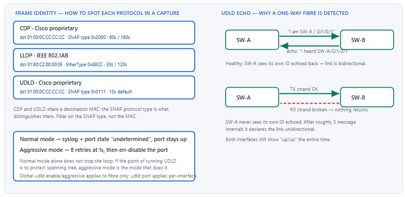
What Do CDP, LLDP, and UDLD Each Actually Do?
How are these three protocols related?
CDP and LLDP are neighbour discovery protocols: each device periodically announces its identity, capabilities, and port details on every enabled interface, and each device caches what it hears until a hold timer expires. They build an inventory, nothing more — neither one changes forwarding behaviour. UDLD is not a discovery protocol at all. It uses a similar Layer 2 advertisement to establish which device and port sits at the far end, then continuously checks that the far end is echoing its identity back. When the echo stops while the interface remains up, UDLD concludes the link is unidirectional and either logs it or shuts the port down.
A Deeper Dive into Scope, Encapsulation, and Defaults
Discovery versus protection, and why the distinction matters
A discovery protocol failing is an inconvenience: your topology map is stale. A protection protocol failing is an outage: a unidirectional fibre between two switches means one side keeps sending BPDUs that the other never receives, so the far side unblocks a port it should have kept blocked, and a Layer 2 loop forms. Spanning tree cannot detect this on its own, because from its perspective the link is simply silent — and silence on a link that is physically up is exactly what Loop Guard and UDLD exist to interpret.
This is why enabling CDP and LLDP everywhere is a documentation decision, while enabling UDLD is a resilience decision with a different risk profile. Getting UDLD wrong takes ports down. Getting it absent lets loops form.
Encapsulation, and how to filter for each in a capture
CDP and UDLD share the same destination multicast MAC address, 01:00:0C:CC:CC:CC, which is the Cisco SNAP-encapsulated multicast group also used by VTP, PAgP, and DTP. What distinguishes them is the SNAP protocol type field: 0x2000 for CDP and 0x0111 for UDLD. Filtering a capture on the destination MAC alone will return all five protocols mixed together. LLDP is easier — it uses its own reserved multicast address and a real EtherType, 0x88CC, so a single-term filter isolates it.
| Property | CDP | LLDP | UDLD |
|---|---|---|---|
| Standard | Cisco proprietary | IEEE 802.1AB | Cisco proprietary |
| Destination MAC | 01:00:0C:CC:CC:CC | 01:80:C2:00:00:0E (nearest bridge) | 01:00:0C:CC:CC:CC |
| Encapsulation | SNAP, protocol type 0x2000 | Ethernet II, EtherType 0x88CC | SNAP, protocol type 0x0111 |
| Default advertisement interval | 60 seconds | 30 seconds | 15 seconds |
| Default hold time | 180 seconds | 120 seconds | Detection at roughly 3 intervals |
| Default state on IOS | Enabled globally and per interface | Disabled globally | Disabled; global form covers fibre only |
| Purpose | Inventory, PoE negotiation, phone provisioning | Inventory across vendors, LLDP-MED provisioning | Detect a link that carries traffic one way only |
| Consequence of failure | Stale topology data | Stale topology data; phones may not get voice VLAN | Undetected loop or black hole |
Why the defaults are what they are
CDP being on by default is a legacy of an era when everything on the wire was Cisco and discovery was purely useful. LLDP being off by default on IOS reflects that it arrived later and Cisco did not want to change existing behaviour. UDLD being off by default reflects the risk asymmetry: a false positive in aggressive mode takes a production link down, so Cisco leaves the decision to the operator. None of these defaults are what you actually want in a modern network, which is why a baseline configuration template should set all three explicitly rather than inheriting.
! Baseline: explicit state for all three, applied to every switch
! Discovery on internally, LLDP on for multi-vendor visibility
cdp run
lldp run
! UDLD on all fibre uplinks, aggressive so it actually stops a loop
udld aggressive
! Recover automatically rather than requiring a truck roll
errdisable recovery cause udld
errdisable recovery interval 300
What these protocols will not do for you
- They do not traverse a router. All three are link-local; a neighbour is the device on the other end of the cable, not two hops away.
- They do not survive a device that does not run them. A media converter, a passive tap, or a transparent optical device will pass frames through and make two switches appear directly adjacent when they are not.
- CDP and LLDP do not validate anything. A host can forge a CDP advertisement claiming to be a switch; nothing authenticates the sender.
- UDLD does not detect a link that is down. It only interprets silence on a link that is up, which is the case a link-state protocol cannot see.
How Does CDP Discover Neighbours, and What Does It Give Away?
What information does a CDP advertisement carry?
A CDP frame is a series of type-length-value fields. Every advertisement carries the Device ID (usually the hostname), the Port ID of the sending interface, and a Capabilities field indicating whether the device is a router, switch, host, or phone. Beyond that CDPv2 typically includes the software version string, the hardware platform, the management IP address, the native VLAN of the port, the duplex setting, the VTP management domain, and — on PoE-capable ports — power request and power available fields. The version string alone identifies the exact IOS release running on the device, which is why CDP on an external-facing port is an audit finding.
A Deeper Dive into CDP Operation, Uses, and Exposure
Timers and cache behaviour
CDP sends an advertisement every 60 seconds by default and tells the receiver to keep the entry for 180 seconds. That three-to-one ratio means two consecutive lost advertisements do not age out a neighbour. It also means a device that is unplugged remains in the cache for up to three minutes, which regularly misleads engineers reading show cdp neighbors immediately after a change. When a port goes down, CDP does flush that neighbour immediately — the stale-entry problem appears when the device stops advertising while the link stays up.
! CDP timers - global, apply to every CDP-enabled interface
cdp timer 60
cdp holdtime 180
! CDPv2 is the default; v1 exists only for very old equipment
cdp advertise-v2
SW1# show cdp neighbors
Capability Codes: R - Router, T - Trans Bridge, B - Source Route Bridge
                  S - Switch, H - Host, I - IGMP, r - Repeater, P - Phone

Device ID        Local Intrfce     Holdtme    Capability  Platform  Port ID
DIST-1.corp.lan  Gig 1/0/49        152          R S I     C9500-40X Gig 1/0/3
SEP0011AABBCCDD  Gig 1/0/12        141          H P M     IP Phone  Port 1
! Holdtme counts DOWN from 180. A value near 180 means a fresh
! advertisement just arrived; near 0 means the neighbour is going quiet.
The detail view, and what an attacker learns from it
The summary output is benign. The detail output is a reconnaissance report.
SW1# show cdp neighbors detail
-------------------------
Device ID: DIST-1.corp.lan
Entry address(es):
  IP address: 10.10.0.2
Platform: cisco C9500-40X,  Capabilities: Router Switch IGMP
Interface: GigabitEthernet1/0/49,  Port ID (outgoing port): GigabitEthernet1/0/3
Holdtime : 154 sec

Version :
Cisco IOS Software [Cupertino], Catalyst L3 Switch Software (CAT9K_IOSXE),
Version 17.9.4a, RELEASE SOFTWARE (fc2)

advertisement version: 2
Native VLAN: 99
Duplex: full
Management address(es):
  IP address: 10.10.0.2
That single command yields the management IP, the exact platform, the exact software version — which maps directly to a published vulnerability list — the native VLAN, and the duplex setting. None of it is authenticated and none of it requires credentials. An attacker with access to any port where CDP is enabled gets it for free.
show cdp interface lists every interface with CDP enabled; compare against your edge port list. Fix: no cdp enable on untrusted interfaces. Do not use global no cdp run unless you also have LLDP, because you will lose phone provisioning and PoE negotiation along with the exposure.
! Disable CDP selectively - keep it internally, drop it at the edge
interface GigabitEthernet1/0/48
 description ---- ISP handoff ----
 no cdp enable
!
interface range GigabitEthernet1/0/1 - 40
 description ---- user access ----
 ! Keep CDP here only if Cisco phones need it; otherwise disable
 no cdp enable
!
! Nuclear option - only if nothing depends on CDP
!   no cdp run
CDP's operational uses that are not documentation
Three things depend on CDP in a Cisco-centric network, and disabling it globally breaks all of them. Cisco IP phones use CDP to learn the voice VLAN so they can tag their own traffic while the attached PC stays untagged on the access VLAN. Cisco PoE devices use CDP power TLVs to negotiate a power budget beyond what 802.3af classification alone signals, which lets a switch allocate precisely rather than reserving the class maximum. And several Cisco management platforms build their topology map from CDP, so an inventory system may go blind.
! Voice VLAN provisioning via CDP - the phone learns VLAN 200 from CDP
interface GigabitEthernet1/0/12
 switchport mode access
 switchport access vlan 100
 switchport voice vlan 200
 spanning-tree portfast edge
 ! CDP must be enabled on this port for the phone to learn the voice VLAN
 cdp enable
! Verify PoE negotiation, which uses CDP power TLVs on Cisco devices
SW1# show power inline GigabitEthernet1/0/12
Interface Admin  Oper       Power   Device              Class Max
                            (Watts)
--------- ------ ---------- ------- ------------------- ----- ----
Gi1/0/12  auto   on         6.3     IP Phone 8845       4     30.0
!
SW1# show power inline GigabitEthernet1/0/12 detail | include Police|Class|Absent
Duplex mismatch detection — a use case people forget
CDP advertises the local duplex setting. If the far end's advertised duplex differs from the local setting, IOS logs a mismatch. On modern all-gigabit networks this rarely fires, but on any link where speed and duplex have been hard-coded on one side and left auto on the other, it is the fastest diagnostic available and it costs nothing.
! The log message CDP generates on a duplex mismatch
%CDP-4-DUPLEX_MISMATCH: duplex mismatch discovered on GigabitEthernet1/0/7
 (not half duplex), with SW2 GigabitEthernet0/1 (half duplex).
! Symptom without CDP: late collisions and terrible throughput,
! diagnosed by reading interface counters instead of one syslog line.
no cdp enable. That policy is expressible in an interface template and survives audit review.no cdp run.How Does LLDP Differ From CDP, and When Do You Need LLDP-MED?
What does LLDP add that CDP does not?
LLDP adds interoperability and extensibility. Because it is IEEE 802.1AB rather than proprietary, a Cisco switch and an Aruba access point or a Dell server NIC can discover each other — something CDP cannot do. Structurally, LLDP defines four mandatory TLVs that every LLDPDU must contain in order: Chassis ID, Port ID, Time To Live, and End of LLDPDU. Everything else is optional, including System Name, System Description, Port Description, System Capabilities, and Management Address. Type 127 is reserved for organisationally specific TLVs, and that extension point is what LLDP-MED, IEEE 802.1 VLAN extensions, and IEEE 802.3 link-aggregation extensions all use.
A Deeper Dive into LLDP Structure, Scope, and MED
The TLV structure, and why order matters for the first three
An LLDPDU is a sequence of TLVs where each has a 7-bit type and a 9-bit length. Chassis ID (type 1), Port ID (type 2), and TTL (type 3) must appear first and in that order; End of LLDPDU (type 0) terminates the frame. A receiver that cannot parse the first three has no way to index the neighbour entry, which is why they are mandatory rather than merely recommended.
| TLV type | Name | Mandatory? | Typical content on a Catalyst |
|---|---|---|---|
| 1 | Chassis ID | Yes | The switch's base MAC address |
| 2 | Port ID | Yes | Interface name, e.g. Gi1/0/12 |
| 3 | Time To Live | Yes | 120 seconds by default |
| 4 | Port Description | No | The interface description string |
| 5 | System Name | No | Hostname |
| 6 | System Description | No | Full software version string — the same exposure as CDP |
| 7 | System Capabilities | No | Bridge, Router, Telephone flags |
| 8 | Management Address | No | Management IP |
| 127 | Organisationally specific | No | LLDP-MED, 802.1 port VLAN ID, 802.3 MAC/PHY and power |
| 0 | End of LLDPDU | Yes | Terminator |
Enabling LLDP, and the per-direction control CDP does not have
LLDP separates transmit from receive. A port can advertise without listening, listen without advertising, or both. That asymmetry is genuinely useful at a security boundary: you can receive a neighbour's advertisement for inventory purposes while advertising nothing about yourself.
! LLDP is globally OFF by default on IOS - enable it explicitly
lldp run
! Timers: interval, TTL (in seconds, not a multiplier), reinit delay
lldp timer 30
lldp holdtime 120
lldp reinit 2
!
! Per-interface direction control - listen but do not advertise
interface GigabitEthernet1/0/48
 description ---- partner handoff ----
 lldp receive
 no lldp transmit
! Trim the TLVs you advertise - drop the version string exposure
interface range GigabitEthernet1/0/1 - 40
 no lldp tlv-select system-description
 no lldp tlv-select management-address
! Verify what is actually being sent
!   show lldp interface GigabitEthernet1/0/1
The three agent scopes and their destination addresses
802.1AB defines three agent types distinguished by destination MAC. The nearest-bridge agent uses 01:80:C2:00:00:0E and is not forwarded by any conformant bridge, so it reaches exactly one hop. The nearest-non-TPMR-bridge agent uses 01:80:C2:00:00:03, and the nearest-customer-bridge agent uses 01:80:C2:00:00:00; both are designed to traverse certain provider-bridge devices to reach a further peer. Cisco Catalyst switches implement the nearest-bridge agent, which is what you want in an enterprise.
Verification output worth reading carefully
SW1# show lldp neighbors
Capability codes:
    (R) Router, (B) Bridge, (T) Telephone, (C) DOCSIS Cable Device
    (W) WLAN Access Point, (P) Repeater, (S) Station, (O) Other

Device ID          Local Intf     Hold-time  Capability      Port ID
DIST-1             Gi1/0/49       120        B,R             Gi1/0/3
AP-FLOOR3          Gi1/0/22       120        B,W             GigabitEthernet0
SEP0011AABBCCDD    Gi1/0/12       180        B,T             Gi1/0/12

Total entries displayed: 3
!
SW1# show lldp neighbors GigabitEthernet1/0/22 detail
------------------------------------------------
Local Intf: Gi1/0/22
Chassis id: 00a2.ee11.3344
Port id: GigabitEthernet0
Port Description: uplink
System Name: AP-FLOOR3
System Description:
Cisco AP Software, ap3g3-k9w8 Version: 17.9.4.30

Time remaining: 97 seconds
System Capabilities: B,W
Enabled Capabilities: B,W
Management Addresses:
    IP: 10.30.4.12
Auto Negotiation - supported, enabled
Physical media capabilities:
    1000baseT(FD)
Media Attachment Unit type: 30
LLDP-MED: provisioning phones without CDP
LLDP-MED is defined by TIA-1057 and carried inside type 127 organisationally specific TLVs. Its most operationally significant element is the Network Policy TLV, which hands an endpoint a VLAN ID, an 802.1p priority, and a DSCP value in one advertisement. That is how a non-Cisco IP phone learns which VLAN to tag its voice traffic with — the job CDP does for Cisco phones. LLDP-MED also carries extended power negotiation, location identification for emergency services, and inventory TLVs.
! LLDP-MED network policy for a multi-vendor phone deployment
interface GigabitEthernet1/0/12
 switchport mode access
 switchport access vlan 100
 switchport voice vlan 200
 spanning-tree portfast edge
 ! MED TLVs: network policy carries the voice VLAN to the phone
 lldp med-tlv-select network-policy
 lldp med-tlv-select power-management
 lldp med-tlv-select inventory-management
SW1# show lldp neighbors GigabitEthernet1/0/12 detail | begin MED
MED Information:
    MED Codes:
          (NP) Network Policy, (LI) Location Identification
          (PS) Power Source Entity, (PD) Power Device
          (IN) Inventory
    H/W revision: 8845-01
    F/W revision: sip8845.14-2-1-0001-71
    Serial number: FCH2401ABCD
    Manufacturer: Cisco Systems, Inc.
    Model: CP-8845
    Capabilities: NP, LI, PD, IN
    Device type: Endpoint Class III
    Network Policy(Voice): VLAN 200, tagged, Layer-2 priority: 5, DSCP: 46
    PD device, Power source: Unknown, Power Priority: High, Wattage: 6.3
    Location - not advertised
show cdp interface Gi1/0/12 voice VLAN against show lldp neighbors Gi1/0/12 detail Network Policy output. Fix: make the two consistent — the switchport voice vlan command drives both, so the usual cause is a leftover manual lldp med-tlv-select policy or a per-port override. Where possible standardise on one protocol per port type.How Does UDLD Detect a Link That Is Broken in Only One Direction?
What is a unidirectional link and why can the hardware not see it?
A unidirectional link is one where frames traverse successfully in one direction and not the other, while both interfaces report up. It happens most often on fibre: one strand of a duplex pair is broken, bent past its radius, or crossed during patching, or a transceiver fails on transmit only. The physical layer does not catch it because each end's receiver still sees light — the local transmitter is fine, so the far end's link detection stays satisfied. UDLD catches it by requiring proof of a return path: each switch sends its own device and port identity, and expects the neighbour to echo that identity back. When the echo stops while the port stays up, the link is unidirectional.
A Deeper Dive into UDLD Modes, Timers, and Alternatives
The echo mechanism, step by step
UDLD first goes through a discovery phase in which each side learns the other's device ID and port ID. Once both sides know each other, each advertisement carries an echo of the neighbour information the sender has cached. Switch A sends "I am A/Gi1/0/1, and I hear B/Gi1/0/2". Switch B checks whether its own identity appears in that echo. If it does, B has proof that its transmissions are reaching A. If A's advertisements arrive but never contain B's identity, then A is not receiving B — the link is unidirectional in the A-to-B receive direction.
This is why UDLD must be running on both ends. A switch with UDLD enabled facing a switch without it will never receive an echo, and depending on mode and code version will either sit in an undetermined state indefinitely or eventually act. Treat single-sided UDLD as not configured.
Normal versus aggressive mode — the decision that matters
In normal mode, when UDLD detects a unidirectional condition it marks the port state undetermined, generates a syslog message, and leaves the port forwarding. That is a monitoring posture. In aggressive mode, when a previously bidirectional neighbour relationship goes silent, UDLD sends eight rapid messages at one-second intervals; if none is acknowledged, it error-disables the port. That is a protection posture.
If the reason you are running UDLD is to prevent spanning-tree loops caused by one-way fibre, normal mode does not achieve it — the loop persists, you just get a log entry about it. Aggressive mode is the mode that satisfies the requirement.
| Aspect | Normal mode | Aggressive mode |
|---|---|---|
| Action on detection | Port state marked undetermined; syslog only | Eight retries at 1-second intervals, then err-disable |
| Loop actually prevented? | No — the port keeps forwarding | Yes — the port is taken out of service |
| Also reacts to a silent neighbour | No | Yes — loss of a previously established neighbour triggers it |
| Risk of false positive | Effectively none | Real — a busy CPU or a code bug can drop advertisements |
| Recommended for | Ports where an outage is worse than a loop | Fibre uplinks between switches, which is most of them |
Where each command form applies — the fibre-only detail
The global commands udld enable and udld aggressive apply only to fibre-optic ports. Copper ports are unaffected by them. To run UDLD on a copper interface you must configure it per interface with udld port or udld port aggressive. This trips people up in labs and in mixed-media deployments, where the global command appears to have been ignored.
! Global form - FIBRE PORTS ONLY. Copper is not covered.
udld aggressive
! Or the monitoring-only global form:
!   udld enable
!
! Per-interface form - works on ANY media including copper
interface TenGigabitEthernet1/1/1
 description ---- fibre uplink to DIST-1 ----
 udld port aggressive
!
interface GigabitEthernet1/0/47
 description ---- copper interswitch link ----
 udld port aggressive
Message interval and detection time
The default message interval is 15 seconds and is configurable from 7 to 90 seconds. Detection takes roughly three message intervals, so the default gives detection in the region of 45 seconds. Lowering the interval to 7 seconds cuts that to roughly 21 seconds at the cost of more control-plane work. Both ends should use the same interval; a mismatch does not break UDLD but makes detection time asymmetric and harder to reason about.
! Faster detection - both ends should match
udld message time 7
!
! Verify the operating interval and per-port state
SW1# show udld GigabitEthernet1/0/47
Interface Gi1/0/47
---
Port enable administrative configuration setting: Enabled / in aggressive mode
Port enable operational state: Enabled / in aggressive mode
Current bidirectional state: Bidirectional
Current operational state: Advertisement - Single neighbor detected
Message interval: 7000 ms
Time out interval: 5000 ms

    Entry 1
    Expiration time: 41000 ms
    Cache Device index: 1
    Current neighbor state: Bidirectional
    Device ID: FDO2345ABCD
    Port ID: Gi1/0/47
    Neighbor echo 1 device: FDO1122WXYZ
    Neighbor echo 1 port: Gi1/0/47
    Message interval: 7000 ms
    CDP Device name: SW2.corp.lan
The line that proves the link is healthy is Neighbor echo 1 port. That is the neighbour telling you it can hear your specific port. Current bidirectional state: Bidirectional is the summary of the same fact. A state of Unknown or Undetermined means the echo is not arriving.
Recovering an error-disabled port
An aggressive-mode shutdown leaves the port in err-disable, which does not clear on its own unless you configure recovery. Two options exist: automatic recovery on a timer, or manual reset. Automatic recovery is generally correct for UDLD because the alternative is a link that stays down after the fibre is repaired until someone notices.
! Automatic recovery after 5 minutes
errdisable recovery cause udld
errdisable recovery interval 300
!
! Manual reset of all UDLD-disabled ports
SW1# udld reset
1 ports shutdown by UDLD were reset.
!
! Or bounce the individual interface
SW1(config-if)# shutdown
SW1(config-if)# no shutdown
!
SW1# show errdisable recovery | include udld
udld                          Enabled          300
UDLD, Loop Guard, and BFD — overlapping but not interchangeable
All three detect a form of "the far end has gone quiet on a link that is up", but they operate at different layers and protect different things. Loop Guard is a spanning-tree feature that acts when BPDUs stop arriving on a non-designated port; it protects only against STP-specific loops and only on ports where STP expects to receive. UDLD is media-aware and protocol-independent, so it also protects links carrying no spanning tree at all — routed interfaces, for instance. BFD detects loss of a bidirectional path at sub-second granularity but must be bound to a routing protocol and does not run on a Layer 2 access link.
| Feature | Layer | Detects | Typical detection time | Action |
|---|---|---|---|---|
| UDLD aggressive | L2, media-aware | One-way link on any port type | ~3 message intervals (45 s default, 21 s at 7 s) | Err-disable the port |
| Loop Guard | L2, STP only | BPDUs stop on a root or alternate port | Max age (20 s default) | Move the port to loop-inconsistent (blocking) |
| BFD | L3, per protocol | Loss of bidirectional forwarding for a routed adjacency | Sub-second, typically 150–450 ms | Signal the client protocol to tear down the adjacency |
| Carrier delay / debounce | L1 | Physical link loss | Immediate to a few seconds | Interface goes down |
Which Discovery and Protection Mistakes Cause Outages or Audit Findings?
What goes wrong most often with these three protocols?
Five things. CDP left on at the network edge leaks software versions and management addresses to anyone with a port. Global no cdp run applied as a security fix breaks voice VLAN assignment and PoE negotiation on Cisco phones. LLDP left off means multi-vendor devices are invisible in inventory and third-party phones never receive a network policy. UDLD configured with the global command on a copper link does nothing at all. And UDLD in aggressive mode without error-disable recovery turns a repaired fibre into a permanently down link until someone logs in.
A Deeper Dive into the Failure Catalogue
The global disable that breaks the phones
The sequence is predictable. An audit flags CDP information disclosure. Someone applies no cdp run globally across the access layer during a maintenance window. Phones reboot overnight as part of a firmware push, come up without a voice VLAN, land untagged on the data VLAN, fail to register, and the helpdesk opens a hundred tickets before anyone connects the two events.
no cdp run as a security remediation Symptom: Cisco IP phones lose their voice VLAN after a reboot and register on the data VLAN or not at all; PoE budgeting reverts to class maximums and the power budget over-subscribes. Cause: CDP was disabled globally, and Cisco phones learn the voice VLAN and negotiate power through CDP. Confirm: show cdp reports "CDP is not enabled"; show power inline shows allocations at class maximum rather than negotiated values. Fix: re-enable CDP globally and disable it per interface on untrusted ports only, or migrate the phones to LLDP-MED first and verify the network policy is being delivered before removing CDP.The UDLD command that silently does nothing
A lab task or a design document says "enable UDLD in aggressive mode on all interswitch links". Someone types udld aggressive globally, sees no error, and moves on. Every copper interswitch link is unprotected, because the global form covers fibre-optic ports only. The configuration looks correct in the running config and the verification command tells the truth if you run it per interface.
! This is what an unprotected copper port looks like AFTER 'udld aggressive'
SW1# show udld GigabitEthernet1/0/47
Interface Gi1/0/47
---
Port enable administrative configuration setting: Follows device default
Port enable operational state: Disabled
Current bidirectional state: Unknown
! ^ 'Follows device default' + 'Disabled' on copper = the global
!   command did not apply. Fix with per-interface 'udld port aggressive'.
! Audit every interswitch link in one pass
SW1# show udld | include Interface|operational state|bidirectional
! Anything showing 'Disabled' or 'Unknown' on a link you believe
! is protected needs the per-interface command.
Single-sided UDLD
UDLD depends on an echo. If the far end is a device that does not run UDLD — a third-party switch, a firewall, a server NIC — no echo will ever arrive. In normal mode the port sits in an undetermined state forever, which is harmless but useless. In aggressive mode the behaviour is more consequential: aggressive mode reacts to the loss of a previously established neighbour, so a port that never establishes one behaves differently from one that had a neighbour and lost it. Either way, UDLD on a link where only one side speaks it provides no protection.
show udld <interface> shows no neighbour entries, or entries that expire; show logging | include UDLD shows the err-disable event. Fix: apply aggressive mode only to links where both ends are known to run UDLD — in practice, Cisco-to-Cisco switch links. For everything else use normal mode or rely on Loop Guard and BFD.Aggressive mode without recovery
Error-disable is a latched state. A fibre repaired at 3 a.m. does not bring the port back; the port stays down until someone runs udld reset or bounces the interface. Configuring automatic recovery converts that from a manual intervention into a self-healing event, at the cost of a port that may flap if the underlying fault is intermittent. The flap is visible in logs, which is better than a silent outage.
! Complete UDLD posture for a switch-to-switch fibre uplink
udld aggressive
udld message time 7
errdisable recovery cause udld
errdisable recovery interval 300
!
interface TenGigabitEthernet1/1/1
 description ---- fibre uplink DIST-1 Te1/1/5 ----
 udld port aggressive
 spanning-tree guard loop
! UDLD takes the port down on a media fault; Loop Guard covers the
! case where BPDUs stop for a reason UDLD does not see.
Trusting the cache after a change
Both CDP and LLDP hold entries until a timer expires. Reading show cdp neighbors thirty seconds after unplugging a device still shows it, and reading it thirty seconds after plugging one in may not show it yet. This produces a specific and common troubleshooting error: concluding that a newly patched link is dead because the neighbour has not appeared, when in fact the first advertisement is up to 60 seconds away. Clear the table explicitly rather than waiting or guessing.
! Force a fresh view rather than reading a stale cache
SW1# clear cdp table
SW1# clear lldp table
! Then wait one advertisement interval before drawing conclusions:
!   CDP  - up to 60 seconds
!   LLDP - up to 30 seconds
!
! Counters tell you whether frames are moving at all
SW1# show cdp traffic
SW1# show lldp traffic
| Failure | First symptom | Confirming command | Fix |
|---|---|---|---|
| CDP enabled at the edge | Audit finding: software version disclosure | show cdp interface |
no cdp enable per untrusted interface |
Global no cdp run |
Phones lose voice VLAN and PoE negotiation | show cdp, show power inline |
Re-enable globally; disable per interface instead |
| LLDP never enabled | Non-Cisco devices missing from inventory; third-party phones untagged | show lldp |
lldp run, plus lldp med-tlv-select network-policy |
| Global UDLD on copper | Link believed protected is not | show udld <intf> shows Disabled |
Per-interface udld port aggressive |
| UDLD aggressive, one side only | Port err-disables under far-end load | show udld <intf> has no neighbour |
Normal mode, or enable UDLD on both ends |
| No err-disable recovery | Repaired fibre stays down until manual reset | show errdisable recovery |
errdisable recovery cause udld |
| Stale discovery cache | New link appears dead; removed device appears present | show cdp traffic / clear cdp table |
Clear the table, wait one interval |
Conclusion
The instinct to group CDP, LLDP, and UDLD together is understandable — they run at the same layer, they use similar frame formats, they all depend on the far end cooperating — but it produces bad decisions. CDP and LLDP answer a question about identity, and their failure mode is a stale map. UDLD answers a question about integrity, and its failure mode is a forwarding loop or a black hole. The correct posture for the first two is a security posture: advertise the minimum, to the fewest ports, in the direction that serves a purpose. The correct posture for the third is a resilience posture: enable it where both ends support it, in the mode that actually takes action, with recovery configured so the network heals itself.
The recurring technical detail worth carrying away is scope. CDP is on everywhere by default and needs to be turned off selectively rather than globally, because voice VLAN assignment and PoE negotiation depend on it. LLDP is off everywhere by default and separates transmit from receive, which is a control CDP does not offer and which is exactly what an external handoff needs. UDLD has two command forms with different media scope, and the global one silently ignores copper — a detail that turns a configuration audit into a false pass. None of these are subtle once known, and all three are routinely wrong in production networks.
Build the habit of verifying per interface rather than globally. show cdp interface, show lldp interface, and show udld <interface> each tell you the operational state on that specific port, and the operational state is the only thing that matters — the running configuration can be entirely correct and the protocol still not applied, which is the single most common outcome with UDLD on copper. Put those three commands into your interswitch link checklist alongside duplex, MTU, and trunk allowed-VLAN, and this whole class of problems disappears before it reaches production.
External Links Recommendations
- IEEE 802.1AB — Station and Media Access Control Connectivity Discovery: the LLDP standard, including TLV formats and the three agent scopes.
- Cisco — Understanding and Configuring the Unidirectional Link Detection Protocol: the echo mechanism, normal versus aggressive mode, and detection timing.
- Cisco — Using the Cisco Discovery Protocol: CDP TLVs, timers, and per-interface control.
- Cisco — Spanning-Tree Protocol Enhancements using Loop Guard and BPDU Skew Detection: how Loop Guard complements UDLD and why it is not a substitute.
- Catalyst 9300 Network Management Configuration Guide: current CDP, LLDP, and LLDP-MED command syntax on IOS-XE.
- RFC 5880 — Bidirectional Forwarding Detection (BFD): the Layer 3 alternative referenced in the comparison, for routed links.
- Cisco Learning Network — CCIE Enterprise Infrastructure: current blueprint and lab equipment details.
Reference Notes
- IEEE Std 802.1AB — LLDP frame format: mandatory TLVs Chassis ID (type 1), Port ID (type 2), Time To Live (type 3), and End of LLDPDU (type 0), in that order.
- IEEE Std 802.1AB — optional TLVs Port Description (4), System Name (5), System Description (6), System Capabilities (7), Management Address (8), and organisationally specific (127).
- IEEE Std 802.1AB — the three LLDP agent destination addresses: nearest bridge 01:80:C2:00:00:0E, nearest non-TPMR bridge 01:80:C2:00:00:03, nearest customer bridge 01:80:C2:00:00:00.
- TIA-1057 — LLDP-MED extensions, including the Network Policy TLV carrying VLAN ID, Layer 2 priority, and DSCP to an endpoint.
- Cisco, "Using the Cisco Discovery Protocol" — CDP default advertisement interval of 60 seconds and hold time of 180 seconds; SNAP encapsulation with protocol type 0x2000 to destination MAC 01:00:0C:CC:CC:CC.
- Cisco, "Understanding and Configuring the Unidirectional Link Detection Protocol" — the echo mechanism, and detection at approximately three times the message interval.
- Cisco, "Understanding and Configuring the Unidirectional Link Detection Protocol" — default message interval of 15 seconds, configurable range 7 to 90 seconds.
- Cisco, "Understanding and Configuring the Unidirectional Link Detection Protocol" — aggressive mode sends eight retries at one-second intervals before error-disabling the port.
- Cisco Catalyst IOS-XE Network Management Configuration Guide —
udld enableandudld aggressiveapply to fibre-optic ports only;udld portapplies per interface regardless of media. - Cisco Catalyst IOS-XE Network Management Configuration Guide — LLDP defaults: transmit interval 30 seconds, hold time 120 seconds, reinitialisation delay 2 seconds; LLDP globally disabled by default.
- Cisco, "Spanning-Tree Protocol Enhancements using Loop Guard and BPDU Skew Detection" — Loop Guard scope and its complementary relationship with UDLD on switch-to-switch links.
- Cisco Learning Network, CCIE Enterprise Infrastructure v1.1 blueprint — placement of Layer 2 discovery and protection protocols within the Network Infrastructure domain.