

Multiple Spanning Tree is the only Layer 2 loop-prevention protocol that lets a campus carry four thousand VLANs on a topology that the control plane only has to compute a handful of times. Every other option forces a trade: classic 802.1D gives you one topology for everything and wastes half your uplinks, while Rapid PVST+ gives you per-VLAN load balancing at the cost of one state machine, one BPDU stream, and one set of timers per VLAN. On a 1,000-VLAN aggregation pair that arithmetic turns into thousands of BPDUs per second and a convergence event that ripples through the CPU for seconds. MST collapses that work into instances, and in the CCIE Enterprise Infrastructure lab it is the protocol that separates candidates who memorized commands from candidates who understand how a region actually forms.
An advanced MST lab is really a test of three things: whether you can make a set of switches agree that they belong to the same region, whether you can steer traffic by manipulating the right instance rather than the wrong VLAN, and whether you can survive the boundary where MST meets a legacy Rapid PVST+ domain. A region forms only when the configuration name, the revision number, and the VLAN-to-instance mapping table are byte-for-byte identical on every switch — the mapping is compared as an MD5 digest, so a single VLAN in the wrong instance silently turns an interior link into a boundary link. Inside a region, only the IST (instance 0) transmits BPDUs; every other MSTI rides along as an M-record inside that single frame. Outside the region, the entire region collapses into one virtual bridge in the Common Spanning Tree. Get those three facts right and 90% of MST troubleshooting becomes mechanical.
This article builds an advanced MST lab from the ground up and then breaks it on purpose. Section one lays out the topology, the addressing, and the pre-flight configuration you need before a single spanning-tree mode mst lands on a device. Section two dissects region formation, the digest, and the CIST/IST/MSTI hierarchy so that later output makes sense. Section three walks the full multi-region build with load balancing across two instances. Section four covers verification — which show command answers which question, and what healthy output looks like. Section five catalogues the design errors that take production networks down: digest mismatch, PVST simulation inconsistency, root guard on the wrong port, and max-hops exhaustion in a deep region.
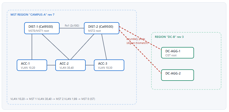
What Do You Need in Place Before You Build an Advanced MST Lab?
What are the prerequisites for a working MST topology?
You need four things before MST will behave predictably. First, an identical VLAN database on every switch in the region — VLANs that exist on one switch and not another will not break the region, but they will make your verification output disagree. Second, a documented VLAN-to-instance plan committed to paper before configuration, because the mapping is hashed and cannot be partially applied. Third, deterministic Layer 1: all trunks explicitly configured as switchport mode trunk with a pruned allowed-VLAN list, and all point-to-point links running full duplex so RSTP link-type detection works. Fourth, a root-bridge plan that names a primary and secondary for every instance including instance 0.
A Deeper Dive into Lab Preparation and Baseline Configuration
Choosing the platform and the software behaviour it implies
MST behaves consistently across Cisco platforms in its protocol operation, but the CLI and the defaults differ enough to burn you. Catalyst 9000 running IOS-XE, Catalyst 3850/3650 running IOS-XE, and Nexus running NX-OS all support 802.1s MST, but NX-OS enables spanning-tree mode rapid-pvst by default and requires an explicit switch to MST, while IOS-XE Catalyst boxes default to Rapid PVST+ as well. Neither defaults to MST. In a virtual lab, CML's IOSv-L2 image supports MST with the classic Catalyst command set, which is sufficient for practising region formation, boundary behaviour, and load balancing.
The one platform difference that reliably produces wrong lab answers is path-cost method. Some platforms compute MST costs with the 16-bit 802.1D table and some with the 32-bit 802.1t table, and a mixed region produces root-port selections that look arbitrary. Pin it explicitly on every switch rather than trusting the default, and verify it before you start attributing behaviour to priorities.
! Baseline on every switch in the region - do this before enabling MST
! Pin the path cost table so every switch computes the same numbers
spanning-tree pathcost method long
! Turn on the protections that MST does not give you for free
spanning-tree portfast edge bpduguard default
spanning-tree loopguard default
! UDLD catches the unidirectional fibre that STP alone cannot
udld enable
Building an identical VLAN database
MST does not require identical VLAN databases, but troubleshooting does. If VLAN 40 exists only on DIST-2, then show spanning-tree mst 2 on ACC-1 will not list it and you will spend ten minutes deciding whether the mapping failed. Create the full set everywhere, then prune on the trunk rather than in the database.
vlan 10
 name USERS-A
vlan 20
 name VOICE-A
vlan 30
 name USERS-B
vlan 40
 name VOICE-B
vlan 99
 name MGMT
Trunk hygiene that MST silently depends on
Two trunk settings change MST behaviour in ways that are easy to miss. Dynamic trunking (DTP) can leave a link in access mode long enough for MST to compute a topology that then changes when the trunk forms, producing a topology-change flood you did not expect. And a mismatched native VLAN on a boundary link toward a Rapid PVST+ domain changes which VLAN carries the untagged IEEE BPDU, which is exactly the frame the PVST simulation logic inspects.
! Deterministic trunk - no DTP, explicit allowed list, explicit native VLAN
interface range GigabitEthernet1/0/1 - 4
 switchport trunk encapsulation dot1q
 switchport mode trunk
 switchport nonegotiate
 switchport trunk native vlan 999
 switchport trunk allowed vlan 10,20,30,40,99
 spanning-tree link-type point-to-point
%SPANTREE-2-RECV_PVID_ERR followed by %SPANTREE-2-BLOCK_PVID_LOCAL. Cause: MST sends its IST BPDU untagged on the native VLAN; a PVST+ neighbour with a different native VLAN receives it on the wrong PVID and declares an inconsistency. Confirm: show interfaces trunk and compare the Native vlan column on both ends, then show spanning-tree inconsistentports. Fix: set the same native VLAN on both ends of every boundary trunk, and keep that VLAN out of the user data path.Port-channel considerations before MST comes up
Bundle first, then enable MST. An EtherChannel presents a single logical port to spanning tree, so a bundle that forms after MST has converged triggers an unnecessary topology change and a cost recalculation. Configure LACP with channel-group mode active on both ends, confirm the bundle is in SU state, and only then change spanning-tree mode.
! Bundle the DIST-1 to DIST-2 links before switching to MST
interface range TenGigabitEthernet1/1/1 - 2
 switchport trunk encapsulation dot1q
 switchport mode trunk
 switchport trunk allowed vlan 10,20,30,40,99
 channel-group 1 mode active
!
interface Port-channel1
 switchport mode trunk
 switchport trunk allowed vlan 10,20,30,40,99
 spanning-tree link-type point-to-point
Writing the mapping plan before touching the CLI
The VLAN-to-instance mapping is the input to an MD5 digest. There is no partial application and no negotiation: either every switch produces the same digest or the link becomes a boundary. Write the plan out, including the VLANs you are deliberately leaving in instance 0, then apply it as a single copy-paste block on every switch. Deviating by one VLAN on one switch is the single most common cause of a broken lab.
| Instance | VLANs | Primary root | Secondary root | Design intent |
|---|---|---|---|---|
| MST 0 (IST) | 1, 99, and all unmapped VLANs | DIST-1 (pri 4096) | DIST-2 (pri 8192) | Carries management and every VLAN not explicitly mapped; also the only instance that sends BPDUs |
| MST 1 | 10, 20 | DIST-1 (pri 4096) | DIST-2 (pri 8192) | Left-hand uplink set forwards; data and voice for the A-side user population |
| MST 2 | 30, 40 | DIST-2 (pri 4096) | DIST-1 (pri 8192) | Right-hand uplink set forwards; achieves uplink load balancing without per-VLAN state |
show command except show spanning-tree mst configuration digest.How Does MST Actually Form a Region and Map VLANs to Instances?
What makes two switches members of the same MST region?
Three parameters must match exactly: the configuration name, the revision number, and the VLAN-to-instance mapping table. The mapping is not carried verbatim in the BPDU — it is compressed into a 16-byte MD5 digest that travels in the MST Configuration Identifier field. A receiving switch compares its own name, revision, and locally computed digest against the values in the BPDU. If all three match, the link is internal to the region and MSTI information is processed. If any one differs, the port becomes a boundary port, the neighbour is treated as a separate region, and only the CIST — the Common and Internal Spanning Tree — runs across that link.
A Deeper Dive into Region Formation, the Digest, and the CIST Hierarchy
The MST configuration identifier, field by field
The MST Configuration Identifier is 51 bytes inside the MSTP BPDU: one byte of format selector, 32 bytes of configuration name, two bytes of revision level, and 16 bytes of configuration digest. The format selector is zero for 802.1s. The name is a plain text string, case sensitive and whitespace significant — CAMPUS-A and campus-a are different regions, and so are CAMPUS-A and CAMPUS-A with a trailing space. The revision is a 16-bit integer with no semantics beyond equality; it exists so that operators can force a region split during a migration without changing the name.
The digest is where the interesting failures live. It is an MD5 hash computed over a 4096-entry table where each entry is the two-byte instance number for that VLAN ID, keyed with a fixed signature key defined in the standard. Because it is a hash, you cannot recover the mapping from it; you can only compare it. Two switches with completely different mappings produce two different 128-bit values and there is no diagnostic hint about where they diverged.
! The three region parameters, applied identically on every member switch
spanning-tree mode mst
!
spanning-tree mst configuration
 name CAMPUS-A
 revision 7
 instance 1 vlan 10,20
 instance 2 vlan 30,40
 exit
Why the default digest is worth memorising
When every VLAN is mapped to instance 0 — that is, when you have enabled MST but configured no instances — the digest takes a well-known constant value: 0xAC36177F50283CD4B83821D8AB26DE62. Seeing that value in show spanning-tree mst configuration digest on a switch you believe you configured means one of two things: the mapping block never applied, or you typed it inside the configuration sub-mode and left without committing. On IOS, the MST configuration sub-mode is transactional — changes take effect when you exit, and are discarded by abort.
! Transactional behaviour of MST config mode - this is a real trap
Switch(config)# spanning-tree mst configuration
Switch(config-mst)# instance 3 vlan 50
Switch(config-mst)# abort
! ^ every change since entering the sub-mode is discarded, no warning
!
Switch(config-mst)# instance 3 vlan 50
Switch(config-mst)# show pending
! ^ shows the uncommitted table; 'show current' shows what is running
Switch(config-mst)# exit
! ^ commit happens here, and only here
CIST, IST, and MSTI — three names that describe one tree and many sub-trees
The Common and Internal Spanning Tree is the single loop-free topology that spans every region and every legacy STP bridge in the network. Inside a region, the portion of the CIST that connects the region's own switches is called the Internal Spanning Tree, and it is instance 0. The CIST root is the bridge with the lowest bridge ID anywhere in the network; the CIST regional root is the bridge inside your region with the lowest cost to the CIST root, and it is the device that presents the region to the outside world.
Every other instance — MST 1, MST 2, and so on — is region-local. An MSTI has no meaning outside its region and its BPDU information is never propagated beyond a boundary port. This is why an MSTI root bridge election is always contained: no matter what a switch in region DC-B advertises, it cannot become the MST 1 root for region CAMPUS-A.
| Concept | Scope | Carried in BPDU as | Elects | Fails when |
|---|---|---|---|---|
| CIST | Entire bridged network, across all regions and legacy bridges | The BPDU body itself (CIST root, external path cost, CIST regional root) | One CIST root for the whole network | A legacy bridge with priority 0 hijacks the root outside your control |
| IST (MST 0) | One region | Same BPDU body; internal root path cost field | The CIST regional root inside the region | Unmapped VLANs land here unnoticed and follow the wrong path |
| MSTI (MST 1..n) | One region only | M-record appended to the IST BPDU, 16 bytes each | A region-local root per instance | Root priority set on the wrong instance number, so nothing changes |
One BPDU, many instances: the M-record
MST sends exactly one BPDU per port regardless of how many instances exist. The IST information occupies the standard BPDU body, and each additional MSTI contributes a 16-byte MSTI Configuration Message — an M-record — appended after it. Each M-record carries that instance's regional root ID, internal root path cost, bridge priority, port priority, and remaining hop count. This is the whole efficiency argument for MST: 64 instances cost one frame, whereas 64 VLANs under Rapid PVST+ cost 64 frames on every port every two seconds.
Hop count replaces message age inside the region
Classic STP ages BPDU information using Message Age against Max Age. MST does not use Message Age inside a region; it uses a hop count that starts at the configured maximum on the regional root and decrements by one at each switch. The default maximum is 20 hops, configurable with spanning-tree mst max-hops. Information whose hop count reaches zero is discarded, which caps the diameter of a region independently of timer values. Message Age still applies to the CIST across boundary links, which is why an extremely deep multi-region design can hit the classic diameter limit even though each region is individually small.
! Region diameter control - set on the regional root, propagates in BPDUs
spanning-tree mst max-hops 20
! Timers are global to MST, not per-instance
spanning-tree mst hello-time 2
spanning-tree mst forward-time 15
spanning-tree mst max-age 20
Boundary ports and what actually crosses them
A boundary port is any port whose received BPDU indicates a different region, or that receives legacy 802.1D/PVST+ BPDUs, or that receives no BPDU at all from an MST peer. Across a boundary, the region behaves as a single virtual bridge: all MSTIs inside the region follow whatever the CIST decides for that boundary port. If the CIST blocks a boundary port, every instance is blocked on it — you cannot load balance across a region boundary using MSTIs, only using the CIST or a Layer 3 design.
show spanning-tree mst interface Te1/1/1 detail and look for Boundary in the port role line, then compare instance states — they will all match the CIST state. Fix: either extend the region so both switches are inside it, or move the inter-site link to Layer 3 and load balance with ECMP.How Do I Configure a Multi-Instance MST Lab Step by Step?
What is the correct order of operations for an MST build?
Configure in this order: baseline path-cost method and protections, VLAN database, trunks and port-channels, then the MST region block, then spanning-tree mode mst, then root priorities per instance, then edge-port and protection tuning. Applying the region block before switching modes means the digest is already correct the moment MST starts, so the region forms in one convergence event instead of two. Setting root priorities last avoids a mid-build root migration. On a live network, reverse the risk by scheduling the mode change itself as the single disruptive step — every switch changing mode causes a full reconvergence of that switch's ports.
A Deeper Dive into the Multi-Instance Build
Applying the region block on every member
This block is identical on DIST-1, DIST-2, ACC-1, ACC-2, and ACC-3. Nothing in it is device specific. Paste it verbatim; do not retype it.
! ===== Identical on all five CAMPUS-A switches =====
spanning-tree mst configuration
 name CAMPUS-A
 revision 7
 instance 1 vlan 10,20
 instance 2 vlan 30,40
 exit
!
spanning-tree mode mst
Setting roots per instance, and why priority 0 is a bad habit
Bridge priority in MST occupies the top four bits of the bridge ID, so it is configurable only in multiples of 4096. The lower twelve bits carry the extended system ID, which for MST holds the instance number rather than a VLAN ID. That means the effective priority you see in show output is your configured value plus the instance number — a switch configured with priority 4096 for MST 2 displays 4098. This is normal and is not a misconfiguration.
Use 4096 for primary and 8192 for secondary rather than 0. Priority 0 leaves you no room to insert a better root during a migration, and it makes an accidentally-connected switch with priority 0 indistinguishable from your intended root. Reserve 0 for emergencies.
! ===== DIST-1: root for IST and MST 1, backup for MST 2 =====
spanning-tree mst 0 priority 4096
spanning-tree mst 1 priority 4096
spanning-tree mst 2 priority 8192
! ===== DIST-2: root for MST 2, backup for IST and MST 1 =====
spanning-tree mst 0 priority 8192
spanning-tree mst 1 priority 8192
spanning-tree mst 2 priority 4096
spanning-tree mst 1 root primary computes a priority lower than the current root and applies it. It is fine for a lab and dangerous in production, because the value it picks depends on what it saw at the moment you typed it. If the real root later changes, your "primary" is a hard-coded number that no longer means primary. Configure explicit priorities in any configuration you intend to keep.Steering traffic with port cost and port priority — on the right instance
Root bridge priority decides the shape of the tree from the top down. To influence a single access switch's uplink choice without moving a root, adjust the cost or priority on the instance you care about. Cost is evaluated on the switch computing its root port; port priority is evaluated on the upstream neighbour and only breaks ties when the sending bridge has two links into the same neighbour.
! ===== ACC-3: prefer the DIST-2 uplink for MST 2 only =====
interface GigabitEthernet1/0/2
 ! Lower cost on this port for instance 2 makes it the MST 2 root port
 spanning-tree mst 2 cost 10000
!
interface GigabitEthernet1/0/1
 ! Leave instance 1 preferring the DIST-1 uplink at default cost
 spanning-tree mst 1 cost 20000
| Tuning knob | Evaluated by | Scope of effect | Command | Use when |
|---|---|---|---|---|
| Bridge priority | Every switch in the instance | Whole instance topology | spanning-tree mst 1 priority 4096 |
You are placing or moving a root bridge |
| Port cost | The local switch selecting its root port | One switch, one instance | spanning-tree mst 1 cost 20000 |
A single access switch should prefer a different uplink |
| Port priority | The upstream neighbour, as a tiebreak | One link pair between two bridges | spanning-tree mst 1 port-priority 64 |
Two parallel links to the same neighbour and equal cost |
| Path-cost method | Every switch independently | All instances on that switch | spanning-tree pathcost method long |
Always — set it identically region-wide |
Path cost values you should know cold
The lab will hand you a topology with mixed link speeds and expect you to predict the root port without running the command. The two cost tables differ by three orders of magnitude, and mixing them produces nonsense.
| Link speed | 802.1D short cost (16-bit) | 802.1t long cost (32-bit) | Practical consequence |
|---|---|---|---|
| 10 Mbps | 100 | 2,000,000 | Irrelevant today except on legacy management links |
| 100 Mbps | 19 | 200,000 | Under short costs, five 100M hops beat one 1G hop |
| 1 Gbps | 4 | 20,000 | Short-cost granularity collapses here; long costs stay meaningful |
| 10 Gbps | 2 | 2,000 | Short costs cannot distinguish 10G from 20G bundles |
| 100 Gbps | 2 (floor) | 200 | Only the long table can express modern speed ratios |
Edge ports, and the difference between PortFast and an edge port
In RSTP and MST vocabulary, an edge port transitions to forwarding immediately and does not generate topology change notifications. Cisco implements this with PortFast. The subtlety is that an edge port loses its edge status the instant it receives a BPDU, and unless BPDU Guard is enabled it then rejoins the normal state machine — which means a rogue switch plugged into a PortFast port can quietly become part of your topology. Enable BPDU Guard globally so that event errdisables the port instead.
! ===== Access ports on ACC-1 / ACC-2 / ACC-3 =====
interface range GigabitEthernet1/0/10 - 48
 switchport mode access
 switchport access vlan 10
 ! Edge behaviour: immediate forwarding, no TCN generated
 spanning-tree portfast edge
 ! Explicit BPDU guard - do not rely on the global default alone
 spanning-tree bpduguard enable
Root Guard and Loop Guard placement in a two-tier region
Root Guard belongs on designated ports facing downstream — the distribution ports toward access switches — where a superior BPDU should never legitimately arrive. Loop Guard belongs on root ports and alternate ports, where the failure mode is the sudden absence of BPDUs on a still-up link. The two are mutually exclusive on a single port because they contradict each other: Root Guard reacts to hearing too much, Loop Guard to hearing nothing.
! ===== DIST-1 downlinks: protect the root from an access-layer switch =====
interface range GigabitEthernet1/0/1 - 3
 spanning-tree guard root
!
! ===== ACC-1 uplinks: protect against a unidirectional link =====
interface range GigabitEthernet1/0/1 - 2
 spanning-tree guard loop
 udld port aggressive
BKN* state and the log shows %SPANTREE-2-ROOTGUARD_BLOCK: Root guard blocking port GigabitEthernet1/0/1 on MST0. Users on that switch lose connectivity until the port ages out. Cause: Root Guard was applied to a port that faces the root; the new, better root BPDU arriving there is exactly what Root Guard exists to reject. Confirm: show spanning-tree inconsistentports lists the port with reason Root Inconsistent. Fix: remove spanning-tree guard root from any port that could ever be a root port; apply it only to downstream-facing designated ports.Joining the second region
Region DC-B uses a different name and revision on purpose, so the inter-region links are boundary ports. The configuration is unremarkable — what matters is that you set the CIST priority deliberately so the CIST root lands where you designed it, rather than wherever the lowest MAC address happens to be.
! ===== DC-AGG-1 and DC-AGG-2 =====
spanning-tree mst configuration
 name DC-B
 revision 3
 instance 1 vlan 100-199
 exit
!
spanning-tree mode mst
! DC-AGG-1 is the intended CIST root for the entire network
spanning-tree mst 0 priority 0
root primary macro is the difference between a design and a snapshot.How Do I Verify That an MST Region Converged the Way I Designed It?
Which show commands answer which question?
Four commands cover almost everything. show spanning-tree mst configuration proves the three region parameters and prints the mapping table; add digest to compare the hash against a neighbour. show spanning-tree mst gives a per-instance summary of root, cost, and port roles — this is where you confirm load balancing actually happened. show spanning-tree mst 1 detail exposes per-port timers, hop counts, and boundary status. show spanning-tree inconsistentports is the single fastest way to find a port blocked by a guard feature rather than by the algorithm.
A Deeper Dive into Verification and Structured Troubleshooting
Step one: prove the region before you look at the topology
Never troubleshoot MST port states before confirming region membership. A digest mismatch changes port roles in ways that look like a cost or priority problem, and you will chase the wrong variable for twenty minutes. Run the configuration check on two adjacent switches and compare the digest strings character by character.
DIST-1# show spanning-tree mst configuration
Name      [CAMPUS-A]
Revision  7     Instances configured 3

Instance  Vlans mapped
--------  ---------------------------------------------------------------------
0         1-9,11-19,21-29,31-39,41-4094
1         10,20
2         30,40
-------------------------------------------------------------------------------

DIST-1# show spanning-tree mst configuration digest
Name      [CAMPUS-A]
Revision  7     Instances configured 3
Digest              0x8C4F3B21D9A07E5613C82F44A9B0D7E1
Pre-std Digest      0x5A19E7C0B3D84621F70A9C25E8B41D36
Digest will not match yours but its behaviour will match your Pre-std Digest. The fix is spanning-tree mst pre-standard on the interface facing the legacy device, which tells the local switch to send pre-standard-formatted BPDUs on that port.Step two: confirm the per-instance topology matches the design
The summary view tells you three things at once: which bridge is root for each instance, what your cost to that root is, and which ports are Root, Designated, Alternate, or Backup. On ACC-3 in the reference lab, MST 1 should show the DIST-1 uplink as Root and the DIST-2 uplink as Alternate, and MST 2 should show the reverse. If both instances show the same root port, load balancing did not happen.
ACC-3# show spanning-tree mst

##### MST0    vlans mapped:   1-9,11-19,21-29,31-39,41-4094
Bridge        address 00a1.b2c3.d4e5  priority  32768 (32768 sysid 0)
Root          address 0011.2233.4455  priority  4096  (4096 sysid 0)
              port    Gi1/0/1         path cost 0
Regional Root address 0011.2233.4455  priority  4096  (4096 sysid 0)
              internal cost 20000     rem hops 19
Operational   hello time 2, forward delay 15, max age 20, txholdcount 6
Configured    hello time 2, forward delay 15, max age 20, max hops 20

Interface        Role Sts Cost      Prio.Nbr Type
---------------- ---- --- --------- -------- --------------------------------
Gi1/0/1          Root FWD 20000     128.1    P2p
Gi1/0/2          Altn BLK 20000     128.2    P2p

##### MST1    vlans mapped:   10,20
Bridge        address 00a1.b2c3.d4e5  priority  32769 (32768 sysid 1)
Root          address 0011.2233.4455  priority  4097  (4096 sysid 1)
              port    Gi1/0/1         cost      20000     rem hops 19

Interface        Role Sts Cost      Prio.Nbr Type
---------------- ---- --- --------- -------- --------------------------------
Gi1/0/1          Root FWD 20000     128.1    P2p
Gi1/0/2          Altn BLK 20000     128.2    P2p

##### MST2    vlans mapped:   30,40
Bridge        address 00a1.b2c3.d4e5  priority  32770 (32768 sysid 2)
Root          address 0066.7788.99aa  priority  4098  (4096 sysid 2)
              port    Gi1/0/2         cost      10000     rem hops 19

Interface        Role Sts Cost      Prio.Nbr Type
---------------- ---- --- --------- -------- --------------------------------
Gi1/0/1          Altn BLK 20000     128.1    P2p
Gi1/0/2          Root FWD 10000     128.2    P2p
Three details in that output deserve attention. The sysid value in parentheses is the instance number folded into the bridge ID, which is why MST 2's priority reads 4098 rather than 4096. The rem hops counter shows 19, confirming one hop from the regional root with a maximum of 20. And MST 0 shows path cost 0 for the external cost while the internal cost is 20000 — the region's own root is also the CIST regional root here, so no external path is traversed.
Step three: interrogate a single port when roles look wrong
The detail view is where boundary status, edge status, and the last topology change appear. On a boundary port, the output explicitly says so, and the port's role in every MSTI mirrors the CIST role.
DIST-1# show spanning-tree mst 0 interface TenGigabitEthernet1/1/1 detail

TenGigabitEthernet1/1/1 of MST0 is designated forwarding
Edge port: no             (default)  port guard : none    (default)
Link type: point-to-point (auto)     bpdu filter: disable (default)
Boundary  : internal                    bpdu guard : disable (default)
Bpdus sent 4821, received 4819

Instance Role Sts Cost      Prio.Nbr Vlans mapped
-------- ---- --- --------- -------- -------------------------------
0        Desg FWD 2000      128.1    1-9,11-19,21-29,31-39,41-4094
1        Desg FWD 2000      128.1    10,20
2        Root FWD 2000      128.1    30,40
Step four: separate algorithmic blocking from guard blocking
A port in BLK because it is an alternate port is the protocol working. A port in BKN* is a port the switch has broken deliberately. The inconsistent-ports command distinguishes them instantly and names the reason.
DIST-2# show spanning-tree inconsistentports

Name                 Interface              Inconsistency
-------------------- ---------------------- ------------------
MST0                 GigabitEthernet1/0/7   Root Inconsistent
MST0                 TenGigabitEthernet1/1/2 PVST Simulation Inconsistent

Number of inconsistent ports (segments) in the system : 2
| Inconsistency | Triggered by | Log message | Recovery |
|---|---|---|---|
| Root Inconsistent | Superior BPDU on a Root-Guard-protected port | %SPANTREE-2-ROOTGUARD_BLOCK |
Automatic once superior BPDUs stop for max age |
| Loop Inconsistent | BPDUs stop arriving on a Loop-Guard-protected non-designated port | %SPANTREE-2-LOOPGUARD_BLOCK |
Automatic when a BPDU is received again |
| PVST Simulation Inconsistent | Boundary port receiving inconsistent PVST+ BPDUs across VLANs | %SPANTREE-2-PVSTSIM_FAIL |
Automatic once the neighbour's per-VLAN roots are consistent |
| Type Inconsistent (PVID) | Native VLAN mismatch on a trunk | %SPANTREE-2-RECV_PVID_ERR |
Requires fixing the native VLAN; not self-healing |
Step five: watch a convergence event rather than guessing at it
Topology change counters tell you whether the network is stable and, if not, which port is generating the churn. A healthy region shows a topology change count that increments only when you touch something.
ACC-1# show spanning-tree mst 1 detail | include change|Topology
  Number of topology changes 3 last change occurred 04:12:56 ago
          from GigabitEthernet1/0/1
! A port that appears here repeatedly is your flapping link
!
! Live view of state transitions during a controlled failure test
ACC-1# debug spanning-tree mstp roleset
ACC-1# debug spanning-tree events
! Remember to 'undebug all' - MSTP debugs are chatty on a busy switch
Which MST Design Mistakes Actually Take Production Networks Down?
What are the highest-impact MST failure modes?
Four failure modes account for most real outages. A VLAN left unmapped falls into instance 0 and follows the IST topology, so it forwards on a path nobody designed for it. A digest mismatch after a partial change turns interior links into boundary links, collapsing your load balancing without any error message. A PVST simulation inconsistency at the boundary between MST and Rapid PVST+ blocks a trunk entirely. And a region whose diameter exceeds max-hops silently discards BPDU information at the far edge, leaving switches that believe they are the regional root.
A Deeper Dive into Production Failure Modes and Their Fixes
The unmapped VLAN problem
Every VLAN that is not explicitly mapped to an MSTI belongs to instance 0. This is not an error condition and generates no warning. The consequence is that a VLAN added six months after the design — a new guest network, a new IoT segment — inherits the IST topology, which in a load-balanced design means it forwards over the uplink set intended for only half the traffic. The failure is a capacity failure, not a connectivity failure, so it is usually discovered during an incident rather than during change control.
instance statement, so it defaults to MST 0. Confirm: show spanning-tree mst configuration and check whether the new VLAN ID appears in the instance 0 range. Fix: add it to the intended instance on every switch in the region in the same maintenance window — a partial application is worse than no application, because it changes the digest.Digest mismatch during a phased change
Changing the mapping is inherently disruptive because the digest changes the moment you commit. If you apply the change switch by switch, every switch you have already changed is in a different region from every switch you have not, and the boundary sweeps across your network as you work. During that window, all MSTIs are subordinate to the CIST on the affected links, load balancing disappears, and traffic concentrates on whatever the CIST chose.
The mitigation is to reduce the window, not to eliminate it. Prepare the block for every switch, apply it in rapid succession from a scripted session, and accept one short reconvergence rather than a long asymmetric period. Where the change is large, bump the revision number deliberately at the start so that the intermediate state is unambiguous in the logs.
! Diagnostic: compare digests across the region in one pass
DIST-1# show spanning-tree mst configuration digest | include Digest
Digest              0x8C4F3B21D9A07E5613C82F44A9B0D7E1
!
ACC-2# show spanning-tree mst configuration digest | include Digest
Digest              0x1F73A02BE45D9C86027B4E19D3A5F0C8
! ^ Different values = different regions. The topology output will
!   look like a cost problem, but the cause is one VLAN in the wrong instance.
MST meeting Rapid PVST+ at the boundary
When an MST boundary port faces a Rapid PVST+ domain, the switch replicates its single IST BPDU onto every VLAN so the PVST+ neighbour sees what it expects. This works only if the relationship is consistent across all VLANs: the MST region must be superior for every VLAN, or inferior for every VLAN. If the PVST+ side is root for VLAN 10 but the MST side is root for VLAN 20, the boundary port cannot represent both relationships with one IST BPDU, and the switch blocks the port rather than risk a loop.
! Boundary port toward a legacy Rapid PVST+ distribution pair
interface TenGigabitEthernet1/1/2
 description ---- boundary to legacy RPVST+ block ----
 switchport mode trunk
 switchport trunk allowed vlan 10,20,30,40
 ! Explicitly control PVST simulation rather than leaving it implicit
 spanning-tree mst simulate pvst
! To disable the check on a port where you have proven it is safe:
!  spanning-tree mst simulate pvst disable
%SPANTREE-2-PVSTSIM_FAIL: Blocking root port TenGigabitEthernet1/1/2: Inconsistent inferior PVST BPDU received on VLAN 20. Cause: the PVST+ neighbour is root for some VLANs and not others; MST cannot express a split relationship in one IST BPDU. Confirm: on the PVST+ side run show spanning-tree root and compare the root bridge across VLANs. Fix: make the MST region unambiguously the root for every VLAN on that boundary — set MST 0 priority lower than every per-VLAN root priority on the PVST+ side — or unambiguously inferior for all of them. Disabling the simulation check without fixing the underlying asymmetry invites a loop.Region diameter and hop-count exhaustion
Max-hops defaults to 20 and is set on the regional root, from where it propagates in BPDUs. A region deeper than the configured maximum silently discards information at the far edge: those switches never learn the real regional root and elect themselves, producing two apparent regional roots inside one region. The symptom is bizarre — a correctly configured region whose distant switches disagree about who the root is — and the diagnostic is the rem hops field reaching zero.
! Check remaining hops at the far edge of a deep region
ACC-EDGE-14# show spanning-tree mst 0 | include rem hops
              internal cost 140000    rem hops 1
! ^ One hop from exhaustion. Add a switch below this one and it breaks.
!
! Raise the ceiling on the regional root only - it propagates
DIST-1(config)# spanning-tree mst max-hops 40
Timers, txholdcount, and the BPDU rate limiter
MST inherits RSTP's transmit hold count, which caps how many BPDUs a port may send per hello interval. The Cisco default is 6. On a switch with a very large number of ports undergoing simultaneous transitions, the limiter can delay proposal/agreement exchanges and stretch convergence. Raising it increases CPU load during a topology change, so treat it as a tuning knob of last resort and change it only after confirming with show spanning-tree mst 0 detail that the hold count is actually being hit.
| Failure mode | First symptom operators notice | Fastest confirming command | Corrective action |
|---|---|---|---|
| Unmapped VLAN in IST | Asymmetric utilisation on uplinks for one VLAN | show spanning-tree mst configuration |
Map the VLAN region-wide in one change window |
| Digest mismatch | Load balancing disappears; one uplink carries everything | show spanning-tree mst configuration digest |
Re-apply the identical mapping block everywhere |
| PVST simulation failure | An entire trunk blocks; VLANs on it go dark | show spanning-tree inconsistentports |
Make root ownership consistent across all VLANs on the boundary |
| Hop-count exhaustion | Distant switches claim to be regional root | show spanning-tree mst 0 | include rem hops |
Raise max-hops on the regional root or flatten the region |
| Root Guard on an uplink | Access switch isolated after a planned root move | show spanning-tree inconsistentports |
Move Root Guard to downstream designated ports only |
Conclusion
MST is best understood as a protocol that trades negotiation for agreement. Rapid PVST+ negotiates everything: every switch advertises its own view for every VLAN and the algorithm resolves it. MST refuses to negotiate the one thing that matters most — which VLANs belong to which topology — and instead demands that every switch already knows the answer. That design choice is what makes MST scale, and it is also the source of every characteristic MST failure. The protocol has no way to reconcile a disagreement about mapping, so it does the only safe thing available and treats the disagreeing neighbour as a foreign region.
The methodology that follows from this is narrow and repeatable. Before you look at a port state, prove that the two switches on either end of the link agree on name, revision, and digest. Before you adjust a cost, confirm you are adjusting the instance that carries the VLAN you care about, not the VLAN itself. Before you place a guard feature, ask whether the port's failure mode is hearing too much or hearing nothing, because Root Guard and Loop Guard answer opposite questions. And before you change a mapping in production, accept that the change is atomic in effect but not in application, and compress the application window as tightly as your tooling allows.
What this buys you in a real network is a Layer 2 domain whose control-plane cost is bounded by the number of topologies rather than the number of VLANs, and whose convergence behaviour you can reason about from a diagram rather than from a capture. In the CCIE lab it buys you the ability to read a task, identify which instance the requirement lands on, and configure it once — instead of testing priorities until the output looks right. Build the reference topology above, break each of the five failure modes deliberately, and watch what each show command reports while it is broken. The output patterns are what you will actually recognise under time pressure, and they are far more durable than the command syntax.
External Links Recommendations
- IEEE 802.1Q — Bridges and Bridged Networks: the current standard that absorbed 802.1s; Clause 13 is the MSTP specification including the configuration identifier and digest computation.
- Cisco — Understanding Multiple Spanning Tree Protocol (802.1s): the canonical Cisco explanation of regions, IST, CIST, and boundary behaviour.
- Cisco — Understanding Rapid Spanning Tree Protocol (802.1w): the proposal/agreement and port-role machinery MST inherits wholesale.
- Cisco — Spanning Tree Protocol Root Guard Enhancement: placement rules and recovery behaviour for Root Guard.
- Cisco — Spanning-Tree Protocol Enhancements using Loop Guard and BPDU Skew Detection: why Loop Guard and Root Guard are mutually exclusive on a port.
- Cisco Learning Network — CCIE Enterprise Infrastructure: current blueprint, equipment list, and software versions for the lab exam.
- Catalyst 9500 Layer 2 Configuration Guide: platform-specific MST command reference and defaults for IOS-XE.
Reference Notes
- IEEE Std 802.1Q, Clause 13 — Multiple Spanning Tree Protocol: definition of the MST Configuration Identifier (format selector, 32-byte name, 16-bit revision, 16-byte digest).
- IEEE Std 802.1Q, Clause 13 — computation of the MST configuration digest as an HMAC-MD5 over the 4096-entry VLAN-to-instance table using the standard signature key.
- IEEE Std 802.1Q, Clause 13 — CIST, IST, and MSTI definitions; the rule that MSTI information does not propagate beyond a region boundary.
- IEEE Std 802.1Q, Clause 13 — MSTI Configuration Message (M-record) format appended to the MST BPDU.
- IEEE Std 802.1t — 32-bit path cost values, replacing the 16-bit table of the original 802.1D.
- Cisco, "Understanding Multiple Spanning Tree Protocol (802.1s)" — region membership requirements and boundary port behaviour on Catalyst platforms.
- Cisco, "Understanding Multiple Spanning Tree Protocol (802.1s)" — pre-standard MST interoperability and the
spanning-tree mst pre-standardinterface command. - Cisco, "Understanding Rapid Spanning Tree Protocol (802.1w)" — edge ports, link type, proposal/agreement, and transmit hold count.
- Cisco, "Spanning Tree Protocol Root Guard Enhancement" —
%SPANTREE-2-ROOTGUARD_BLOCKbehaviour and automatic recovery after max age. - Cisco, "Spanning-Tree Protocol Enhancements using Loop Guard and BPDU Skew Detection" — Loop Guard applicability to root and alternate ports only.
- Cisco Catalyst 9500 Layer 2 Configuration Guide (IOS-XE 17.x) — MST command syntax, default timers (hello 2 s, forward delay 15 s, max age 20 s), and default max-hops of 20.
- Cisco Learning Network, CCIE Enterprise Infrastructure v1.1 blueprint — placement of spanning-tree technologies within the Network Infrastructure domain.