Introduce something about RS EXAM technology,and SPOTO CCIE CLUB is good at RS
A lot of human wisdom comes from nature. When students look at a tree carefully, they will find a tree with roots, trunks, tree shrubs, branches, leaves, water through the roots, and continuously transported to the trunk, tree shrew, and then Reach the leaves. Moisture is always unidirectional in the process of spreading from root to leaf; and the leaves, depending on the energy produced by photosynthesis, follow the leaves to the branches, tree shrews, trunks, and roots.
Moisture and energy are flows in opposite directions. If the root is defined as upstream and the leaves are downstream, then water flows from upstream to downstream; and energy flows from downstream to upstream. No matter which direction the flow is, it does not happen in the original place. That is because the physical structure of the tree is divergent. There is no physical interweaving of trunks, tree branches and branches, and naturally, no loop will occur.
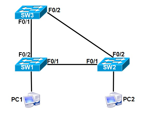
Why does a Layer 2 switching network create a physical loop?
In order to achieve redundancy, bandwidth improvement, or incorrect connection between switches, a closed physical loop is inevitable, and the forwarding mechanism of the Ethernet determines that there can be no physical loops. When there is a loop, the broadcasts are sent to all hosts. Unknown Unicast Frame will be unscrupulously looping around the loop: the mountains are not edged, the heavens and the earth are combined, and the loop is absolute! These frames can never reach the destination, and it is a fatal blow to the switch CPU. If there is a loop, you may not be able to log in to your switch locally or remotely. Only restart or unplug the line, is it a bit wolf...
Layer 2 switch forwarding mechanism
The switch learns its source MAC X from the incoming frame on a port N, and generates a MAC Address Table as follows:
MAC X <------> Port N
In this way, it will generate a mapping table of MAC address and Port. If a Frame is received, it will query the Destination MAC of the Frame to match the MAC Address Table, and if it matches, it will be sent out from the corresponding Port.
If there is no match, it is considered to be unknown Unicast or broadcast. There is no way to send it out from all ports (except the interface that receives the Frame). The other switch also handles this, so the frame is always in a closed loop. An infinite loop in the road.
Spanning Tree Spanning Tree
Network scientists have discovered this law. There is a bold idea. Since there is a physical loop in the Layer 2 network, a logical way is used to break the physical loop and form a divergent tree structure. Will not loop indefinitely? The answer is yes, and it is done.
If the topology of the tree is used for the Layer 2 switching network, select a root bridge in the Layer 2 network, and the other switches act as tree trees. Each tree has a root port. This is a root port. It is the upstream interface of the switch. Except for the root tip, the other interfaces are downstream interfaces. As for whether the downstream interface is unblocked or blocked, depending on the path cost to the root, who is closer to the root, who will be smooth (Forwarding) That is often referred to as Designated Port; who is far from the root, who needs to be blocked (Blocked), commonly known as Non-Designated Port. Through this bionic mechanism, network loops can be effectively avoided.
Spanning tree election mechanism
As for who is doing the root bridge, the priority is high, then it is the boss, all the ports of the boss are designed, there is nothing to say, then each switch chooses its own closest root port, how close is the quantitative measurement? With cost, the cost is small. Then the younger brothers selected designed on the interconnected port, it is also simple, use cost to compare size, who is small who wins, so designated.
The algorithmic process of the spanning tree protocol can be summarized in three steps: selecting the root bridge, selecting the root port, and selecting the designated port.
(1) Select the root bridge: select a root bridge in the whole network.
Compare the BID value of the bridge. The smaller the value, the higher the priority. The ID value is composed of two parts: the priority of the switch and the MAC address. If the priority of the switch is the same, the MAC address is compared. The smaller the address value, the more the node is elected as the root bridge.
(2) Select the root port: select the root port on each non-root switch
First, compare the cost of the root path. The cost of the root path depends on the bandwidth of the link. The larger the bandwidth and the lower the path cost, the port is selected as the root port.
Second, if the cost of the root path is the same, compare the BID value of the peer switch. The smaller the value, the higher the priority.
Finally, compare the port ID value, which is divided into two parts: port priority and port number, and the value are selected as the root port.
(3) Select the designated port: select one designated port on each link, all ports on the root bridge are designated ports
First, compare the root path costs.
Second, compare the ID value of the bridge where the port is located.
Finally, compare the port's ID value.

 Join Telegram Study Group ▷
