

The EIGRP composite metric is usually described as combining bandwidth, delay, load, reliability, and MTU. Two of those five are wrong. MTU is carried in the update and used for path MTU purposes but has never been an input to the metric calculation. Load and reliability are inputs in principle, but their coefficients default to zero and switching them on is a reliable way to make a stable network oscillate. What actually computes a metric on a default Cisco router is bandwidth and delay, and nothing else — two terms, one formula, and a scaling factor of 256.
Knowing the formula precisely matters because every EIGRP design decision downstream of it depends on the numbers it produces. Whether a backup path qualifies as a feasible successor is an arithmetic comparison between an advertised distance and a feasible distance. Whether variance admits a path is another. Whether two paths load balance equally depends on whether their metrics are identical to the last digit. And the single most common metric mistake — tuning bandwidth instead of delay — happens precisely because people know the formula contains a bandwidth term without knowing that the bandwidth command is read by half a dozen other subsystems while the delay command is read by almost nothing else.
This article works through the arithmetic and its consequences. Section one gives the classic formula in full, with the interface defaults and worked examples. Section two explains what each K coefficient weights and why three of the five are zero by design. Section three covers wide metrics — the 64-bit formula, the 65536 scale factor, picosecond delay, K6, and the RIB scaling divisor. Section four is tuning: which knob to turn, by how much, and how the change propagates. Section five is the failure catalogue, from K-value mismatches that drop adjacencies to tunnel defaults that starve EIGRP of bandwidth.
delay would have influenced alone.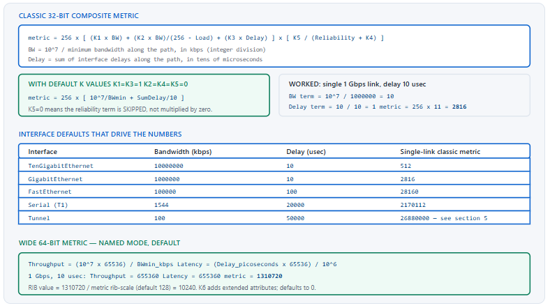
What Is the EIGRP Composite Metric Formula?
What does the full formula look like and what survives the defaults?
The classic composite metric is 256 multiplied by a bracket containing a bandwidth term, a load term, and a delay term, optionally multiplied by a reliability term. The bandwidth term is 107 divided by the smallest interface bandwidth along the path in kilobits per second. The delay term is the sum of all interface delays along the path, expressed in tens of microseconds. With the default coefficients — K1 and K3 set to 1, K2, K4 and K5 set to 0 — the load term vanishes and the reliability multiplier is skipped entirely rather than being multiplied by zero. What remains is 256 times the sum of the bandwidth and delay terms.
A Deeper Dive into the Classic Arithmetic
The formula written out
! Full classic composite metric
!
!  metric = 256 x [ (K1 x BW)
!                 + (K2 x BW) / (256 - Load)
!                 + (K3 x Delay) ]
!                 x [ K5 / (Reliability + K4) ]
!
!  BW    = 10^7 / minimum bandwidth in kbps, integer division
!  Delay = sum of interface delays in tens of microseconds
!  Load and Reliability are 8-bit values out of 255
!
! With defaults K1=1 K2=0 K3=1 K4=0 K5=0 this collapses to:
!
!  metric = 256 x [ (10^7 / BWmin) + (SumDelay / 10) ]
Bandwidth takes the minimum, delay takes the sum
This asymmetry is the most consequential property of the formula. The bandwidth term reflects the single narrowest link on the path — a ten-gigabit path with one fast-ethernet segment in the middle is a fast-ethernet path as far as EIGRP is concerned. The delay term accumulates, so every additional hop adds cost regardless of speed. That is why adding hops always raises the metric while adding capacity may change nothing at all, and it is the structural reason a neighbour further from a destination almost always advertises a higher distance — which is exactly what makes the feasibility condition work.
! Three-hop path: Gig, Gig, FastEthernet
!   minimum bandwidth = 100000 kbps  (the FastEthernet)
!   total delay       = 10 + 10 + 100 = 120 usec
!
!   BW term    = 10^7 / 100000 = 100
!   Delay term = 120 / 10      = 12
!   metric = 256 x (100 + 12) = 28672
!
! Compare: replacing the two Gig links with 10 Gig changes nothing,
! because the FastEthernet is still the minimum bandwidth.
!   metric = 256 x (100 + 12) = 28672  -- identical
Reading the components out of the router
The vector metric block in the topology and routing tables shows the raw components before they are combined, which is how you find the one slow link that is dominating a metric.
R1# show ip eigrp topology 10.9.9.0/24
EIGRP-IPv4 Topology Entry for AS(100)/ID(1.1.1.1) for 10.9.9.0/24
  State is Passive, Query origin flag is 1, 1 Successor(s), FD is 28672
  Descriptor Blocks:
  10.0.12.2 (GigabitEthernet0/1), from 10.0.12.2, Send flag is 0x0
      Composite metric is (28672/28416), route is Internal
      Vector metric:
        Minimum bandwidth is 100000 Kbit
        Total delay is 120 microseconds
        Reliability is 255/255
        Load is 1/255
        Minimum MTU is 1500
        Hop count is 3
! ^ Minimum bandwidth 100000 on a supposedly all-gigabit path means
!   there is a FastEthernet or a mis-set 'bandwidth' command in it.
Interface defaults you should know without looking
| Interface type | Default bandwidth (kbps) | Default delay (µs) | Single-link classic metric | Note |
|---|---|---|---|---|
| TenGigabitEthernet | 10,000,000 | 10 | 512 | Bandwidth term is 1 — the floor for classic metrics |
| GigabitEthernet | 1,000,000 | 10 | 2,816 | The reference case in most examples |
| FastEthernet | 100,000 | 100 | 28,160 | Ten times the delay of Gigabit, not just the bandwidth |
| Ethernet (10M) | 10,000 | 1,000 | 281,600 | Rare outside legacy equipment |
| Serial (T1) | 1,544 | 20,000 | 2,170,112 | Delay dominates on serial links |
| Loopback | 8,000,000 | 5,000 | 128,320 | High delay despite high bandwidth |
| Tunnel | 100 | 50,000 | Very large | The default that causes real problems — see section five |
Where the metric comes from for routes EIGRP did not compute
Two categories of route have a metric that no path calculation produced. A redistributed route takes the seed metric supplied at redistribution, expressed as five values in the order bandwidth, delay, reliability, load, MTU — and only the first two of those five actually influence the composite metric, for exactly the reasons covered above. Without a seed metric, redistribution into EIGRP fails silently and the routes never appear, which is the classic redistribution mistake. A locally generated summary takes the best metric among its component prefixes by default, which means the summary's metric changes whenever the best component changes; summary-metric pins it so downstream routers see a stable number.
! Seed metric order: bandwidth delay reliability load MTU
router eigrp CORP
 address-family ipv4 unicast autonomous-system 100
  topology base
   redistribute ospf 1 metric 1000000 100 255 1 1500
   ! bw=1000000 kbps, delay=100 (tens of usec), rel=255, load=1, mtu=1500
   ! Only bandwidth and delay affect the result with default K values.
   summary-metric 10.1.0.0/16 1000000 100 255 1 1500
  exit-af-topology
 exit-address-family
!
! Without a seed metric, nothing is redistributed and no error appears
R1# show ip route eigrp | include 172.20
! (empty) - add the metric keyword or a default-metric statement
!
router eigrp CORP
 address-family ipv4 unicast autonomous-system 100
  topology base
   default-metric 1000000 100 255 1 1500
  exit-af-topology
 exit-address-family
What Does Each K Value Actually Weight?
Why are three of the five coefficients zero?
K1 weights bandwidth and K3 weights delay; both default to 1 because both are static properties of the topology that only change when someone changes a configuration or a link fails. K2 weights load and K4 and K5 weight reliability. All three default to 0 because load and reliability are derived from rolling interface counters that change continuously with traffic. A metric that varies with utilisation produces routing that varies with utilisation, which means the best path moves as soon as traffic follows it there, then moves back — a feedback loop that causes route oscillation and continuous topology recomputation. The defaults exist to prevent that.
A Deeper Dive into the Coefficients
What each coefficient controls
| Coefficient | Weights | Default | Source of the value | Safe to change? |
|---|---|---|---|---|
| K1 | Bandwidth term | 1 | Configured interface bandwidth, minimum along the path | Yes, but rarely useful |
| K2 | Load-scaled bandwidth | 0 | Rolling 5-minute load average, 0–255 | No — causes oscillation |
| K3 | Delay term | 1 | Configured interface delay, summed along the path | Yes, but rarely useful |
| K4 | Reliability offset | 0 | Rolling reliability average, 0–255 | No |
| K5 | Reliability numerator | 0 | Enables the reliability multiplier at all | No |
| K6 | Extended attributes (wide metrics only) | 0 | Jitter and energy, where supported | No — breaks classic interoperability |
The K5 special case
The reliability multiplier is not applied at all when K5 is zero. This is a specific rule rather than a mathematical consequence — multiplying by zero would drive every metric to zero, which is obviously not what happens. The formula is defined so that the trailing bracket is skipped entirely when K5 is 0, which is why the default configuration produces a sensible two-term metric rather than nothing.
! Setting K5 to a non-zero value activates the reliability multiplier
router eigrp CORP
 address-family ipv4 unicast autonomous-system 100
  metric weights 0 1 0 1 1 1
  !             TOS K1 K2 K3 K4 K5
 exit-address-family
! ^ K1=1 K2=0 K3=1 K4=1 K5=1. Now every metric varies with the
!   rolling reliability counter on every interface in the path.
!
! The first argument is TOS and must be 0 - EIGRP never implemented
! multiple TOS values, and a non-zero value is rejected.
Why load-based metrics oscillate
Suppose K2 is enabled and two paths are otherwise equal. Traffic follows path A. Path A's load rises, so its metric rises, so path B becomes better and traffic moves there. Path A's load then falls and path B's rises, so the metric ordering inverts again. The oscillation period is governed by the load averaging interval — five minutes by default — so the network flips every few minutes indefinitely, with a full DUAL recomputation and RIB update each time. Every flow is rerouted mid-session on each flip.
! Observe the inputs that would drive the oscillation
R1# show interfaces GigabitEthernet0/1 | include reliability|load
  reliability 255/255, txload 37/255, rxload 12/255
! ^ txload changes continuously. With K2 non-zero, so does the metric.
!
! The averaging interval, which sets the oscillation period
interface GigabitEthernet0/1
 load-interval 30
! ^ Shortening this makes the oscillation faster, not smaller.
The one case for changing K1 or K3
Setting K1 to zero produces a delay-only metric; setting K3 to zero produces a bandwidth-only metric. Both are legitimate and neither causes oscillation, since both inputs remain static. A delay-only metric is occasionally used on networks where every link is the same speed and the design intent is purely about latency, and it has the side effect of making metric arithmetic trivial. The reason it is still rare is that it must be applied to every router in the autonomous system in one change, and the benefit over simply tuning delay with both coefficients enabled is marginal.
! Delay-only metric: K1=0, K3=1. Apply domain-wide or not at all.
router eigrp CORP
 address-family ipv4 unicast autonomous-system 100
  metric weights 0 0 0 1 0 0
  !             TOS K1 K2 K3 K4 K5
 exit-address-family
!
! metric now = 256 x (SumDelay / 10), with bandwidth ignored entirely
R1# show ip eigrp topology 10.9.9.0/24 | include Composite|Minimum band
      Composite metric is (512/256), route is Internal
        Minimum bandwidth is 100000 Kbit
! ^ The 100 Mbps link no longer raises the metric at all.
K values are compared in the Hello
All K coefficients are carried in EIGRP Hello packets and must match exactly between neighbours. A mismatch prevents the adjacency from forming, with a log message naming the cause. This makes any K-value change a domain-wide operation: every router in the autonomous system must be changed in one window, or the ones you have not touched become isolated.
! The log message when K values disagree
%DUAL-5-NBRCHANGE: EIGRP-IPv4 100: Neighbor 10.0.12.2 (Gi0/1) is down:
 K-value mismatch
!
! Compare all six across the two routers
R1# show eigrp protocols | include Metric weight
  Metric weight K1=1, K2=0, K3=1, K4=0, K5=0, K6=0
R2# show eigrp protocols | include Metric weight
  Metric weight K1=1, K2=1, K3=1, K4=0, K5=0, K6=0
! ^ K2 differs. Revert on R2, or apply everywhere.
metric weights command applied on one router to make a specific path preferred causes every EIGRP adjacency on that router to drop, and the router becomes isolated from the routing domain. Cause: K coefficients are carried in Hellos and compared; a router with different K values cannot form an adjacency with any neighbour. Confirm: show eigrp protocols | include Metric weight on the affected router and any neighbour. Fix: revert immediately. K values are never the right tool for influencing a single path — use delay on the relevant interfaces, which is local, non-disruptive, and does not require domain-wide coordination.metric maximum-hops — but hop count contributes nothing to the composite metric. A route exceeding the maximum is treated as unreachable. In a network where this limit is being approached the real problem is topology depth, not the limit.How Do Wide Metrics Change the Arithmetic?
What is different in the 64-bit formula?
The structure is the same and the numbers are far larger. The throughput term applies a scale factor of 65536 to the same 107-over-bandwidth ratio, so a one-gigabit link contributes 655,360 rather than 10. The latency term uses delay expressed in picoseconds, scaled by 65536 and divided by 106, which for a ten-microsecond interface also yields 655,360. A sixth coefficient K6 is available for extended attributes and defaults to zero. Because the resulting 64-bit value cannot fit the 32-bit metric field in the routing table, it is divided by a RIB scale factor — 128 by default — before installation, which is why the topology table and the routing table show different numbers for the same route.
A Deeper Dive into Wide Metrics
The wide formula, worked
! Wide 64-bit metric with default coefficients
!
!   Throughput = (10^7 x 65536) / minimum bandwidth in kbps
!   Latency    = (delay in picoseconds x 65536) / 10^6
!   metric     = Throughput + Latency        (K1 = K3 = 1)
!
! Single 1 Gbps link, delay 10 microseconds = 10,000,000 picoseconds:
!
!   Throughput = (10,000,000 x 65,536) / 1,000,000 = 655,360
!   Latency    = (10,000,000 x 65,536) / 1,000,000 = 655,360
!   metric     = 1,310,720
!
! RIB value = 1,310,720 / 128 = 10,240
! The same route, two scales
R1# show eigrp address-family ipv4 topology 10.9.9.0/24 | include Composite
      Composite metric is (1310720/0), route is Internal
!
R1# show ip route 10.9.9.0 | include Known via
  Known via "eigrp 100", distance 90, metric 10240
! ^ 1310720 / 128 = 10240. Same metric, RIB scale applied.
Why the scaling was necessary
The classic bandwidth term is 107 divided by the bandwidth in kilobits, using integer division. At ten gigabits that is exactly 1. At forty and one hundred gigabits it is a fraction that floors to the same value. Every link at or above ten gigabits therefore contributes an identical bandwidth term, and the metric loses the ability to distinguish them — a network of mixed 10G, 40G and 100G links prefers paths based purely on accumulated delay and hop count. The 65536 scale factor restores resolution across that range.
! Classic: everything at or above 10G collapses to the same term
!    10 Gbps -> 10^7 / 10,000,000  = 1
!    40 Gbps -> 10^7 / 40,000,000  = 0 -> floored to 1
!   100 Gbps -> 10^7 / 100,000,000 = 0 -> floored to 1
!
! Wide: the same speeds remain distinguishable
!    10 Gbps -> (10^7 x 65536) / 10,000,000  = 65,536
!    40 Gbps -> (10^7 x 65536) / 40,000,000  = 16,384
!   100 Gbps -> (10^7 x 65536) / 100,000,000 = 6,553
Tuning the RIB scale
The divisor trades range against precision. A smaller value preserves more of the 64-bit metric's resolution in the routing table but risks overflowing the 32-bit field on long paths; a larger value is safer but collapses small metric differences into the same RIB value, which can turn unequal-cost paths into apparently equal-cost ones. The default of 128 is a reasonable compromise and should only be changed with a specific reason.
! Increase RIB precision on a network with fine metric differences
router eigrp CORP
 address-family ipv4 unicast autonomous-system 100
  metric rib-scale 64
 exit-address-family
!
! Confirm both the version and the divisor in effect
R1# show eigrp protocols | include Metric
  Metric weight K1=1, K2=0, K3=1, K4=0, K5=0 K6=0
  Metric rib-scale 64
  Metric version 64bit
Interoperating with classic routers
A router computing wide metrics forms adjacencies with one computing classic metrics and exchanges routes correctly; the protocol converts between the representations at the boundary. Two constraints apply. K1 through K5 must match, exactly as always. And K6 must be zero, because a classic router has no concept of it — setting K6 to a non-zero value isolates the router from every classic neighbour. Explicitly forcing the metric version is available where mixed behaviour is causing confusion.
! Force classic 32-bit metrics even in named mode, for a mixed domain
router eigrp CORP
 address-family ipv4 unicast autonomous-system 100
  metric version 32bit
 exit-address-family
! ^ Rarely necessary. Conversion at the boundary normally just works,
!   and forcing 32bit gives up the whole benefit of migrating.
show eigrp protocols | include Metric version on each router. Fix: nothing to fix. Validate on invariants instead — neighbour count, prefix count, and next hop for a sample of destinations — all of which are unchanged across the conversion.How Do I Tune the Metric Correctly?
Which knob should I turn?
Delay, essentially always. The delay command is read by EIGRP and by very little else, so changing it affects routing and nothing more. The bandwidth command is read by QoS percentage-based policies, by SNMP interface speed reporting, by NetFlow utilisation calculations, by bandwidth-percent limits on the routing protocols themselves, and by any tooling that derives capacity from the device. Changing bandwidth to influence a route silently changes all of those. Delay is also cumulative rather than a minimum, which makes its effect additive and predictable: removing a unit of delay reduces the metric by 256 for every router downstream.
A Deeper Dive into Tuning
The units, and the arithmetic of a change
The delay interface command takes a value in tens of microseconds. A Gigabit interface defaults to delay 1 in command units, displayed as DLY 10 usec. Because the delay term is the sum divided by ten and the whole bracket is multiplied by 256, each unit of command-level delay contributes exactly 256 to the metric. That gives a clean rule for sizing a change: to move a metric by N, adjust delay by N divided by 256 units.
! Units: the command takes TENS of microseconds
interface GigabitEthernet0/1
 delay 1
! -> displayed as DLY 10 usec, contributes 256 to the metric
!
interface GigabitEthernet0/2
 delay 20
! -> displayed as DLY 200 usec, contributes 5120 to the metric
!
R1# show interfaces GigabitEthernet0/2 | include DLY
  MTU 1500 bytes, BW 1000000 Kbit/sec, DLY 200 usec,
Which direction the change propagates
Delay on an interface affects the metric computed by every router that uses that interface in its path, in the direction away from it. Raising the delay on your own outbound interface raises your total metric through that neighbour, which influences your own successor selection and the variance threshold. It does not change what the neighbour advertises to you. To change an advertised distance you must change delay somewhere on the path the neighbour itself uses.
! Goal: make R1 prefer the R3 path over the R2 path
!
! Option A - raise the cost of the path you do NOT want, locally
R1(config)# interface GigabitEthernet0/1
R1(config-if)# delay 50
!   Affects R1's total metric via R2. Local, immediate, reversible.
!
! Option B - lower the cost of the path you DO want, upstream
R3(config)# interface GigabitEthernet0/1
R3(config-if)# delay 5
!   Lowers what R3 advertises to R1, which also affects every other
!   router downstream of R3. Wider blast radius.
!
! Verify which one you actually got
R1# show ip eigrp topology 10.9.9.0/24 | include Composite
      Composite metric is (3072/1792), route is Internal
      Composite metric is (15872/1792), route is Internal
! ^ AD unchanged at 1792 = Option A. A changed AD = Option B.
Why not bandwidth
| Subsystem | Reads bandwidth |
Reads delay |
Consequence of changing bandwidth |
|---|---|---|---|
| EIGRP metric | Yes | Yes | Intended effect |
| OSPF cost (auto-cost) | Yes | No | OSPF cost changes on the same interface |
| QoS percentage-based policies | Yes | No | Reserved bandwidth in every class changes |
EIGRP bandwidth-percent |
Yes | No | EIGRP's own transmission budget changes |
SNMP ifSpeed / monitoring |
Yes | No | Utilisation graphs become wrong |
| NetFlow utilisation | Yes | No | Capacity reports become wrong |
| Interface load calculation | Yes | No | txload and rxload become wrong |
! The collateral damage from a bandwidth change, made visible
R1(config)# interface Serial0/0/0
R1(config-if)# bandwidth 512
!
R1# show policy-map interface Serial0/0/0 | include Class|bandwidth
    Class-map: VOICE (match-any)
      bandwidth 30% (153 kbps)
! ^ Was 463 kbps when bandwidth was 1544. The QoS reservation just
!   shrank by two thirds because someone wanted a different EIGRP path.
offset-list: tuning specific prefixes instead of whole interfaces
Changing delay affects every prefix that crosses the interface. When the requirement is narrower — make this one prefix less attractive, leave everything else alone — offset-list is the correct tool. It adds a fixed value to the metric of routes matched by an access list, either inbound or outbound, optionally scoped to one interface. The offset is added directly to the composite metric, so the arithmetic is straightforward: an offset of 512 raises the matched metric by 512, equivalent to two units of delay but applied only where you asked.
The trade is that an offset-list is invisible unless you go looking for it. A metric that does not match the topology and does not match the interface delays is almost always an offset-list somewhere, and it is the last place most people check.
! Make one prefix less attractive inbound on one interface only
access-list 10 permit 10.9.9.0 0.0.0.255
!
router eigrp CORP
 address-family ipv4 unicast autonomous-system 100
  topology base
   offset-list 10 in 5120 GigabitEthernet0/1
  exit-af-topology
 exit-address-family
!
! Classic mode syntax, under router configuration mode
router eigrp 100
 offset-list 10 in 5120 GigabitEthernet0/1
!
! Verify the offset landed - the metric jumps by exactly the offset
R1# show ip eigrp topology 10.9.9.0/24 | include Composite
      Composite metric is (8192/1792), route is Internal
! ^ Was 3072. 3072 + 5120 = 8192. Note the AD is unchanged, so an
!   inbound offset does NOT affect feasibility - only the total.
Tuning inside a named-mode configuration
Delay and bandwidth remain interface commands even in named mode — they are physical properties, not EIGRP properties, and other protocols read them. What moves into af-interface is EIGRP's own behaviour on the interface, including the bandwidth percentage it will consume.
! Physical properties stay on the interface
interface GigabitEthernet0/2
 bandwidth 1000000
 delay 20
!
! EIGRP behaviour lives in af-interface
router eigrp CORP
 address-family ipv4 unicast autonomous-system 100
  af-interface GigabitEthernet0/2
   bandwidth-percent 40
   hello-interval 5
   hold-time 15
  exit-af-interface
 exit-address-family
delay value with no explanation is indistinguishable from a mistake, and the next engineer will normalise it during a cleanup. Put the reason in the interface description or an adjacent comment in your configuration management, because the command carries no metadata and the effect is invisible until a path changes.Which Metric Mistakes Break Routing or Adjacencies?
What are the highest-impact errors?
Five. A K-value change applied to one router isolates it, because the coefficients are compared in Hellos. Tuning bandwidth instead of delay silently reconfigures QoS, monitoring, and EIGRP's own transmission budget. Leaving a tunnel interface at its default bandwidth of 100 kbps gives EIGRP a transmission budget of 50 kbps, which stalls updates on any topology of size. A mis-set bandwidth anywhere on a path becomes the minimum for every route across it, producing metrics nobody can explain. And enabling load or reliability coefficients creates a routing loop between traffic and topology that never settles.
A Deeper Dive into the Failure Catalogue
The tunnel bandwidth default
A tunnel interface defaults to 100 kbps of bandwidth and 50,000 microseconds of delay. Two things follow. The metric across the tunnel is enormous, which is usually harmless because every tunnel has the same problem. Far more damaging is that EIGRP limits itself to 50 percent of the interface bandwidth by default, which on a 100 kbps tunnel is 50 kbps — not enough to flood a large topology table, so updates queue, acknowledgements are delayed, the queue count climbs, and routes go stuck-in-active on a link that has gigabits of real capacity underneath it.
! Default tunnel values - both need attention
R1# show interfaces Tunnel0 | include BW|DLY
  MTU 17916 bytes, BW 100 Kbit/sec, DLY 50000 usec,
!
! Set the bandwidth to something representative of the real path...
interface Tunnel0
 bandwidth 100000
 ip mtu 1400
 ip tcp adjust-mss 1360
!
! ...and give EIGRP a sensible share of it
router eigrp CORP
 address-family ipv4 unicast autonomous-system 100
  af-interface Tunnel0
   bandwidth-percent 20
  exit-af-interface
 exit-address-family
! ^ 20% of 100000 kbps = 20 Mbps for EIGRP. Ample.
bandwidth-percent is the default 50, so EIGRP throttles itself to 50 kbps regardless of the real capacity. Queries and replies queue behind updates and miss the active timer. Confirm: show ip eigrp neighbors detail shows a persistently non-zero Q Cnt and rising Retrans on the tunnel. Fix: set a realistic bandwidth on the tunnel and an appropriate bandwidth-percent. On a hub facing many spokes, size the percentage against the aggregate the hub must serve, not against one spoke.A stray bandwidth statement poisoning every path across it
Because the bandwidth term takes the minimum along the whole path, one interface with an artificially low bandwidth raises the metric of every prefix reachable through it, on every router downstream. The symptom is a set of metrics that make no sense against the topology diagram, and the vector metric block names the culprit immediately.
! Every route across this path shows an implausible minimum bandwidth
R1# show ip eigrp topology 10.9.9.0/24 | include Minimum bandwidth
        Minimum bandwidth is 512 Kbit
! ^ On an all-gigabit path. Something has 'bandwidth 512' on it.
!
! Find it - check every interface along the path
R2# show interfaces | include ^[A-Z].*is up|BW
GigabitEthernet0/1 is up, line protocol is up
  MTU 1500 bytes, BW 512 Kbit/sec, DLY 10 usec,
! ^ Left over from a circuit that was upgraded years ago.
Asymmetric metrics from one-sided delay changes
Delay is configured per interface and per direction. Changing it on one end of a link and not the other produces a path whose cost differs depending on which way you traverse it, and EIGRP is perfectly happy with that — nothing compares the two, and no message is generated. The result is asymmetric routing: traffic leaves via one path and returns via another, which is harmless between routers and fatal anywhere a stateful device sits in the path. Because the two ends are configured independently and often by different people at different times, this accumulates quietly over years.
! Compare both ends of the same link
R1# show interfaces GigabitEthernet0/1 | include DLY
  MTU 1500 bytes, BW 1000000 Kbit/sec, DLY 200 usec,
!
R2# show interfaces GigabitEthernet0/1 | include DLY
  MTU 1500 bytes, BW 1000000 Kbit/sec, DLY 10 usec,
! ^ Same link, 20x difference in one direction. Deliberate or not,
!   it makes forward and return paths diverge for every prefix.
!
! Audit every non-default delay on a router in one pass
R1# show running-config | include ^interface|^ delay
Hop count exhaustion
The default maximum hop count is 100. A route arriving with a hop count at or above the maximum is treated as unreachable, silently. This is rarely hit in an enterprise but does occur in networks with deep chains of tunnels or in labs where routes loop through many devices. The limit is configurable up to 255, though a topology approaching it usually has a design problem rather than a limit problem.
! Raise the limit if the topology genuinely warrants it
router eigrp CORP
 address-family ipv4 unicast autonomous-system 100
  metric maximum-hops 200
 exit-address-family
!
! Check what the current hop count is on a distant prefix
R1# show ip eigrp topology 10.9.9.0/24 | include Hop count
        Hop count is 3
| Mistake | Symptom | Confirming command | Fix |
|---|---|---|---|
| K values changed on one router | All adjacencies on that router drop | show eigrp protocols | include Metric weight |
Revert; use delay instead |
| K2, K4 or K5 enabled | Routes flap every few minutes under load | show ip eigrp events shows repeated recomputation |
Return all three to 0 domain-wide |
| Bandwidth tuned for routing | QoS reservations and monitoring silently wrong | show policy-map interface; compare against intent |
Restore bandwidth; tune delay |
| Tunnel left at default bandwidth | SIA and queue buildup on an idle circuit | show ip eigrp neighbors detail — Q Cnt |
Set bandwidth and bandwidth-percent |
| Stray low bandwidth on a path | Implausible metrics network-wide | Vector metric — Minimum bandwidth | Correct the interface bandwidth |
| Hop count exceeded | Distant prefixes silently unreachable | Vector metric — Hop count | metric maximum-hops, or fix the topology |
| Wide vs classic confusion | Metrics differ by orders of magnitude | show eigrp protocols | include Metric version |
Nothing — validate on invariants |
Conclusion
The EIGRP metric is a two-term sum wearing a five-term formula. Bandwidth contributes the minimum along the path, delay contributes the sum, everything is scaled by 256, and the load and reliability terms that appear in every textbook rendering are switched off by coefficients that should stay at zero. Understanding that is enough to predict any metric in a topology by hand, which in turn is enough to reason about feasible successors, variance thresholds, and equal-cost load balancing without running a command.
Two consequences deserve to be carried forward. The first is the asymmetry between the two live terms: adding hops always raises the metric because delay accumulates, while adding capacity often changes nothing because bandwidth takes the minimum. That is why the feasibility condition works at all — a router further from a destination almost always advertises a higher distance — and it is why upgrading one link in a path frequently produces no routing change whatsoever. The second is that wide metrics exist for a specific arithmetic reason: integer division of ten million by the bandwidth in kilobits stops discriminating at ten gigabits, and everything faster collapses to the same value.
Operationally the discipline reduces to one rule with one exception. Tune with delay, because it is read by EIGRP and almost nothing else and because its effect is additive and predictable at 256 per unit. Never tune with K values, because they are compared in Hellos and a mismatch isolates the router rather than influencing a path. The exception is bandwidth on tunnel interfaces, where the default of 100 kbps needs correcting not for the metric but because it starves EIGRP's own transmission budget. Build a three-hop lab, compute each metric by hand before looking, then check the vector metric block. When your arithmetic matches the router's, the rest of EIGRP becomes considerably easier to reason about.
External Links Recommendations
- RFC 7868 — Cisco's Enhanced Interior Gateway Routing Protocol (EIGRP): Section 5.5 defines the classic composite metric and Section 5.6 the wide-metric extension.
- Cisco — Introduction to EIGRP: the metric formula, the K coefficients, and worked calculations.
- Cisco — EIGRP Wide Metrics: the 64-bit metric, K6, and the
metric rib-scaledivisor. - Cisco — EIGRP Stub Routing: how metric and query behaviour interact in hub-and-spoke designs.
- Cisco IOS-XE EIGRP Configuration Guide: current syntax for
metric weights,metric rib-scale,metric maximum-hops, andbandwidth-percent. - Cisco — How Does Unequal Cost Path Load Balancing Work in IGRP and EIGRP?: how the computed metric feeds the variance and feasibility tests.
- Cisco Learning Network — CCIE Enterprise Infrastructure: current blueprint and lab equipment list.
Reference Notes
- RFC 7868, Section 5.5 — the classic composite metric formula, including the scaling by 256 and the treatment of the reliability term when K5 is zero.
- RFC 7868, Section 5.5 — default coefficient values K1 = K3 = 1 and K2 = K4 = K5 = 0.
- RFC 7868, Section 5.5 — bandwidth is the minimum along the path and delay is the cumulative sum of interface delays.
- RFC 7868, Section 5.6 — wide metrics: 64-bit representation, the K6 coefficient, and increased delay precision.
- RFC 7868, Section 5.6.2 — the wide-metric throughput and latency computations and the EIGRP_WIDE_SCALE factor of 65536.
- RFC 7868, Section 5.6.2 — the RIB scale factor used to fit a 64-bit metric into the 32-bit routing table field.
- RFC 7868, Section 6.5 — K values are carried in Hello packets and neighbours with mismatched values do not form an adjacency.
- RFC 7868, Section 5.3 — maximum hop count enforcement and the treatment of routes exceeding it as unreachable.
- Cisco, "Introduction to EIGRP" — MTU is carried in the vector metric for informational purposes and is not an input to the composite metric.
- Cisco IOS-XE EIGRP Configuration Guide — the
delayinterface command is expressed in tens of microseconds; thebandwidthcommand in kilobits per second. - Cisco IOS-XE EIGRP Configuration Guide —
bandwidth-percentdefaults to 50 and limits EIGRP's own transmission rate as a proportion of configured interface bandwidth. - Cisco IOS-XE Interface Configuration Guide — tunnel interfaces default to 100 kbps bandwidth and 50,000 microseconds of delay.