 Join Telegram Study Group ▷


This page introduces BGP and MPLS protocols and mentions the functional differences between BGP and MPLS protocols used in VPN (Virtual Private Network). BGP represents the Border Gateway Protocol. MPLS represents multi-protocol label exchange.
About Virtual Private Network:
It extends a private network through a shared infrastructure. A VPN facilitates the interconnection of geographically independent sites with the same privacy and reliability to a secure private network. See the working principle of the VPN.
There are different types of VPNs:
• Traditional VPNs: Focused on Frame Relay (Layer 2) and ATM (Layer 2)
• CPE-based VPNs: Based on L2TP and PPTP (Layer 2) and IPSec (Layer 3)
• Provider-Provisioned VPNs (PP-VPNs): Based on MPLS-based Layer 2 VPNs, BGP/MPLS VPNs or RFC2547bis (Layer 3)
We will introduce the BGP / MPLS VPN network components and architecture based on RFC2547bis. We will also show how BGP / MPLS VPN works on controlling flow and data flow between two sites. BGP / MPLS VPN solves the following two common problems.
• There will be a problem with VPNs having a large number of sites.
• Moreover, to add a new site, all the existing sites need to be configured.
The BGP / MPLS VPN type solves extension and configuration problems and allows thousands of VPN, to support hundreds of sites per VPN. It also supports overlapping address spaces. This model does not allow traffic from one VPN to be visible in another VPN.
Note: if you want to study further the BGP and MPLS technology, and you can contact us now. We have valuable study materials and certification exam answers and questions.

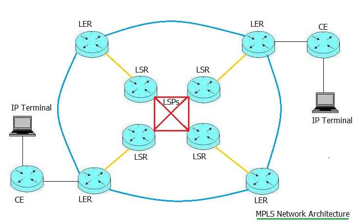
BGP/MPLS VPN Network Topology and Components
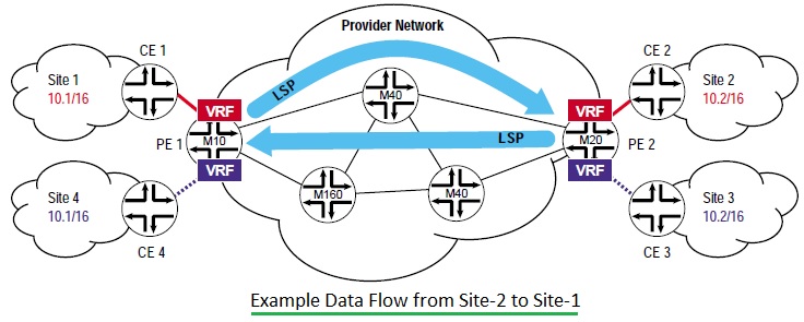
The following are the main BGP / MPLS VPN network components, as shown in figure 1. This figure is used only for the description of Junibo Networks. It includes CE (customer Edge) router, PE (Provider Edge) router and P (provider) router. Here are some useful points about these network components.
• The following are the main BGP / MPLS VPN network components, as shown in figure 1. This figure is used only for the description of Junibo Networks. It includes CE (customer Edge) router, PE (Provider Edge) router and P (provider) router. Here are some useful points about these network components.
• Only PE routers that interface with the site need to be configured to add or remove new sites. One PE router uses the IBGP protocol to communicate with other PE routers.
• The PE router maintains routing information for sites that are connected to the network. Each PE router maintains a VRF (Virtual Routing and Forwarding) table for each of its connected sites. Each customer is connected. ATM PVC, Frame Relay PVC, and VLANs are mapping to specific VRF.
•P router acts as an LSR (label switching router). It is able to create an LSP (label switching path) between PE routers.
Control Flow and Data Flow, BGP-Border Gateway Protocol | How it works
Let’s take a look at the traffic through a BGP / MPLS VPN. There are two types of traffic. Control flow and data flow. The following steps refer to data from site 2 to site 1 and the control process that occurs before the data flow begins.
The control flow in BGP/MPLS VPN, including two subflows.
• First, responsible for the exchange of routing information between CE and PE and between two PE. CE-1 publishes routing to PE-1 (10.1 / 16). PE-1 installs local routing in VRF red. PE-1 uses the IBGP protocol to publish routes to 10.1 / 16 to PE-2. Here, PE-1 uses MPLS tags (for example, 222) to advertise routes. After receiving the routing notification from PE-1, PE-2 installs the route in VRF red (10.1 / 16). PE-2 later published the route with the prefix 10.1 / 16 to CE-2.
• Second, responsible for the establishment of LSP between PE routers. This is necessary for MPLS protocol to forward VPN traffic on the provider backbone network. LDP and RSVP protocols are used to establish and maintain LSP. on a service provider network, LDP is critical to ensuring multi-vendor interoperability.
Once the control flow is supplemented, the data can flow from one site to another on a dedicated established LSP. The figure illustrates the data flow from site-2 (host-10.2.3.4) to site-1 (server-10.1.3.8). The following are the steps involved in data flow across the BGP / MPLS VPN.
• Host (10.2.3.4) forwards data packets destined for a server (10.1.3.8) to the default gateway (CE-2).
• CE-2 does route lookup and forward it(i.e. IPv4 packet) to PE-2.
• PE-2 looks up the route in VRF-Red to get the MPLS tag (PE-1 publishes the information required by), BGP next hop (PE-1 loopback address), LSP outgoing subinterface (PE-2) to PE-1). With these, user traffic is forwarded from PE-2 to PE-1. using the MPLS protocol with a tag stack (that is, two tags) Here PE-2 will be used as ingress-LSR, PE-1 as the exit of LSP in the data stream-LSR.
• The PE-1 after receiving the packet uses the bottom tag (that is, 222) to identify the CE. directly connected to it In this way, PE-1 forwards the packet (that is, IPv4) to the CE-1.
• CE-1 forward packet to server (10.1.3.8).
MPLS-Multi Protocol Label Switching
• MPLS stands for Multi-Protocol Label Switching.
• MPLS VPN forwards packets based on tags rather than IP.
• In combination with the best combination of the overlay and the peer-to-peer model.
• The p router in the network switches according to the label so as to forward the VPN data flow through the backbone network of the provider.
• There is two table maintenance in the MPLS. FEC table of LER(label edge router(CE)and LIB table of LSR(label switching router).
FEC (Forward Equivalence Class) table = { Destination IP Address, Label Out, Interface }
LIB (Label Information Base) table = { Label-In, Label-Out, Interface }
LIB and FEC tables are built dynamically using LDP (Label Distribution Protocol), MP-BGP (Multiprotocol Border Gateway Protocol) and RSVP-TE (Resource Reservation Protocol with traffic engineering). Refer MPLS Protocol basic tutorial.
About SPOTO
SPOTO focus on online IT Certification training for 16 years. SPOTO offers 100% real and valid Cisco CCNA, CCNP, CCIE, ISC, Amazon AWS, Microsoft, and other IT exam practice tests. And we have many free online training courses of Cisco exam on YouTube. You can find many useful and helpful tips and suggestions. If you’re still worried about to prepare and pass the Cisco exam, try SPOTO now. SPOTO tutors will help you get the CCIE number at the first try.