
 Join Telegram Study Group ▷


This document describes commands for configuring and monitoring multi-protocol label switching (MPLS) functionality on Cisco routers and switches. This document is a supporting file that describes other functional modules of other MPLS application
Finding Feature Information
Information About MPLS
How to Configure MPLS
Additional References
Feature Information for MPLS on Cisco Routers
Glossary
Finding Feature Information
Your software version may not support all the features recorded in this module. For the latest warning and functional information, see Bug Search Tool and release notes for your platform and software versions. To find information about the features recorded in this module and view a list of releases that support each feature, see the function information table at the end of this module.
Information About MPLS
MPLS Overview
Functional Description of MPLS
Label Switching Functions
Distribution of Label Bindings
Benefits of MPLS
MPLS Overview
Multi-protocol label switching (MPLS) combines the performance and function of layer 2 (data link layer) switching with the mature scalability of layer 3 (network layer) routing. MPLS enables service providers to meet the challenge of explosive network utilization while providing opportunities for differentiated services without sacrificing existing network infrastructure. MPLS architecture is very flexible and can use any combination of layer 2 technology. Provide MPLS support for all layer 3 protocols, and extensions may far exceed those commonly provided in today undefined networks.
MPLS effectively enables IP services to be delivered over ATM switched networks. MPLS supports the creation of different routes between sources and destinations on the Internet backbone of a router-only. By incorporating MPLS into its network architecture, service providers can save money, increase revenue and productivity, provide differentiated services and gain competitive advantage.
Join SPOTO to get more latest knowledge of MPLS. And SPOTO offers 100% real and stable Cisco exam dumps to help candidates to pass the exam fast and in the first try.

Functional Description of MPLS
Label switching is a high-performance packet forwarding technology, which integrates the performance and traffic management functions of the data link layer (layer 2) switching with the scalability, flexibility, and performance of network layer (layer 3) routing.
Label Switching Functions
In a conventional Layer 3 forwarding mechanism, each router extracts all information related to the forwarding packet from the Layer 3 header when the packet traverses the network. This information is then used as an index for the routing table lookup to determine the next hop of the packet.
In a conventional Layer 3 forwarding mechanism, each router extracts all information related to the forwarding packet from the Layer 3 header when the packet traverses the network. This information is then used as an index for the routing table lookup to determine the next hop of the packet.
In label switching, layer 3 header analysis is carried out only once. The layer 3 header is then mapped to a fixed-length unstructured value, called a label.
Many different headers can be mapped to the same label, as long as they always lead to the same next-hop selection. In fact, tags represent forwarding equivalents-that is, the forwarding function cannot distinguish between a set of packets, no matter how different they may be.
The initial selection of the tag need not be based on the content of the layer 3 header only; for example, the forwarding decision of a subsequent hop may also be based on routing policy.
After assigning the label, add a short label header in front of the layer 3 packet. The header is transmitted over the network as part of the packet. In subsequent jumps through each MPLS router in the network, the label is switched and the forwarding decision is made by looking up the MPLS forwarding table for the tags carried in the packet header. Therefore, it is not necessary to reevaluate the packet header during packet transmission over the network. Because of the fixed length and unstructured tag, the MPLS forwarding table search process is simple and fast.
Distribution of Label Bindings
Each>Label Switching Router(LSR)in the network makes an independent local decision on the tag value used to represent the forwarding equivalence class. This association is called label binding. Each LSR notifies its neighbor of its label binding. The following protocols help increase the awareness of label binding for adjacent routers:
Label Distribution Protocol (LDP)-enables peer-to-peer LSR in MPLS networks to exchange label binding information, To support hop-by-hop forwarding label distribution protocol (TDP) in MPLS networks-MPLS forwarding resource reservation protocol (RSVP) along normal routing paths-to support MPLS traffic engineering boundary gateway protocol (BGP)-to support MPLS virtual private network (VPN) when tag packets are sent from LSR A to adjacent LSR B, the label value carried by IP packets is the label value assigned by LSR B. To represent the forwarding equivalence class of a packet. Therefore, the tag value changes with the IP packet traversing the network.
Benefits of MPLS
MPLS provides the following major benefits to service provider networks:
Extensible support for virtual private network (VPN)-MPLS enables VPN services to be supported in service provider networks, thus greatly accelerating the growth of the Internet.
The use of VPN in VPN provides an attractive alternative to the construction of VPN through ATM or Frame Relay permanent virtual circuit (PVC) or routers connected to client sites in various forms of the tunnel.
Unlike the PVC VPN model, the MPLS VPN model has a high degree of scalability to accommodate more and more sites and customers. The MPLS VPN model also supports "Any to any" communication between the VPN sites without the need for a full-mesh PVC or a backhaul (sub-optimal route) traffic across the service provider network. For each MPLS VPN user, the service provider undefined network appears to act as a private IP backbone, where users can reach other sites within the VPN organization, but do not have access to any other VPN organizations undefined site.
From the point of view of the user, the MPLS VPN model can greatly simplify network routing. For example, an MPLS VPN user can typically use the backbone of a service provider as a default route to communicate with all other VPN sites without having to manage routes on a complex virtual backbone of many PVCs.
Explicit routing function (also known as constraint-based routing or traffic engineering)-explicit routing adopts "constraint-based routing", where the path of traffic flow is the shortest path to meet the resource requirements (constraints) of traffic flow.
In MPLS traffic engineering, such factors as bandwidth requirements, media requirements and the priority of one traffic flow and another traffic flow can be considered. These traffic engineering features enable administrators of service provider networks
Control traffic flow in the network
Reduce congestion in the network
Make the best use of network resources
Therefore, the network administrator can specify the traffic that is expected to flow between points in the network(thereby establishing a traffic matrix), while relying on the routing system.
Calculate the best paths for network traffic
Set up the explicit paths to carry the traffic
Support for IP routing on ATM switches (also known as IP and ATM integration)-MPLS enables ATM switches to perform almost all the functions of IP routers. This ability of ATM switches stems from the fact that the MPLS forwarding paradigm, that is, label switching, is exactly the same as the forwarding paradigm provided by ATM switch hardware.
The key difference between a traditional ATM switch and an ATM tag switch is the control software used by the latter to establish its virtual channel identifier(VCI)table entry. The ATM tag switch uses IP Routing Protocol and Label Distribution Protocol(TDP)to establish VCI table entries.
ATM label switches can be used as traditional ATM switches. In this dual-mode, ATM switch resources, such as VCI space and bandwidth, are divided between the MPLS control plane and the ATM control plane. The MPLS control plane provides IP-based services, while the ATM control plane supports ATM-oriented functions, such as circuit simulation or PVC services.
Join SPOTO to get more latest knowledge of MPLS. And SPOTO offers 100% real and stable Cisco exam dumps to help candidates to pass the exam fast and in the first try.
How to Configure MPLS
This section explains how to perform the basic configuration required to prepare a router for MPLS switching.
The configuration tasks of other MPLS applications are described in the functional module documentation of the application.
Configuring a Router for MPLS Switching
Verifying Configuration of MPLS Switching
Configuring a Router for MPLS Forwarding
Verifying Configuration of MPLS Forwarding
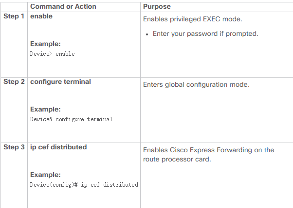
Configuring a Router for MPLS Switching
MPLS switching on Cisco routers requires that Cisco Express Forwarding be enabled.
SUMMARY STEPS
1. enable
2. configure terminal
3. IP CEF distributed
DETAILED STEPS
Verifying Configuration of MPLS Switching
To verify that Cisco Express Forwarding is configured correctly, issue the show ip cef summary command, which produces output similar to that shown below:
SUMMARY STEPS
1. show ip cef summary
DETAILED STEPS
show IP cef summary
Example:
Router# show ip cef summary
IP CEF with switching (Table Version 49), flags=0x0
43 routes, 0 resolve, 0 unresolved (0 old, 0 new)
43 leaves, 49 nodes, 56756 bytes, 45 inserts, 2 invalidations
2 load sharing elements, 672 bytes, 2 references
1 CEF resets, 4 revisions of existing leaves
4 in-place modifications
recounts: 7241 leaves, 7218 node
Adjacency Table has 18 adjacencies
Router#
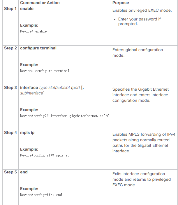
Configuring a Router for MPLS Forwarding
MPLS forwarding on Cisco routers requires IPv4 packet forwarding enabled. For more information about MPLS forwarding commands, see``Multi-Protocol Label Exchange Command Reference undefined.
SUMMARY STEPS
1. enable
2. configure terminal
3. interface type slot/subslot /port [. subinterface]
4. Mpls IP
5. end
DETAILED STEPS
What to Do Next
Configure either of the following:
MPLS Label Distribution Protocol (LDP). For information about configuring MPLS LDP, see the MPLS Label Distribution Protocol Configuration Guide.
Static labels. For information about configuring static labels, see MPLS Static Labels.
Verifying Configuration of MPLS Forwarding
To verify that MPLS forwarding has been configured properly, issue the show mpls interfaces detail command, which generates output similar to that shown below:
SUMMARY STEPS
1. show mpls interfaces detail
DETAILED STEPS
show mpls interfaces detail
Example:
Device# show mpls interfaces detail
Interface GigabitEthernet1/0/0:
IP labeling enabled (ldp)
LSP Tunnel labeling not enabled
MPLS operational
MTU = 1500
Interface POS2/0/0:
IP labeling enabled (ldp)
LSP Tunnel labeling not enabled
MPLS not operational
MTU = 4470