 Join Telegram Study Group ▷


Whether on a Cisco router or a Cisco switch, the standard ACL access control list can't match the characteristics of the source and destination addresses at the same time, nor can it meet the "grained" control requirements of today's network world. This blog post will tell you in detail what is the extending ACLs and the different implementations of extending ACLs.
SPOTO focuses on IT certification training for 16 years and always offers the latest news about IT certification and technology. The main content is as follows.
1. Purpose
1). Understand what an extended ACL is;
2). Understand the difference between standard and extended ACLs;
3). Understand the different implementation methods of extended ACLs;
2. Application Environment
Standard ACLs can only restrict source IP addresses, while extended ACLs have a wide range of restrictions, including source IP, destination IP, and service type.
3. Experiment apparatus
1). DCRS-7604 (or 6804 or 5526S) switch 1
2). DCS-3926S switch 1 set
3). PC 2 sets
4). Console line 1-2 roots
5). a number of straight through the network cable
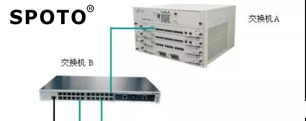
4. Experimental topology:
5. Experimental requirements
Purpose: Disable PC2 telnet switch A.
Divide two port-based VLANs on Switch A and Switch B: VLAN 100 and VLAN 200. Switch A port 1 is set to Trnuk port:
VLAN | IP | Mask |
100 | 192.168.100.1 | 255.255.255.0 |
200 | 192.168.200.1 | 255.255.255.0 |
Trunk port | 1/1 and 1/2 |
The configuration of switch B is as follows:
VLAN | Port member |
100 | 1~8 |
200 | 9~16 |
Trunk port | 24 |
The network settings for PC1-PC4:
device | IP address | gateway | Mask |
PC1 | 192.168.100.11 | 192.168.100.1 | 255.255.255.0 |
PC2 | 192.168.200.22 | 192.168.200.1 | 255.255.255.0 |
verification:
1. Before configuring the ACL, both PC1 and PC2 can telnet switch A.
2. After configuring the ACL, PC1 can telnet switch A, and PC2 cannot telnet switch A. If the experimental results are consistent with the theory, then the experiment is completed.
6. Experimental procedure
Step 1: All switches are restored to factory settings, vlan100 and vlan200 are created in the switch, and ports are added.
Switch B:
switchB(Config)#vlan 100
switchB(Config-Vlan100)#
switchB(Config-Vlan100)#switchport interface ethernet 0/0/1-8
switchB(Config-Vlan100)#exit
switchB(Config)#vlan 200
switchB(Config-Vlan200)#switchport interface ethernet 0/0/9-16
switchB(Config-Vlan200)#exit
switchB(Config)#
Step 2: Set the switch trunk port
Switch B:
switchB(Config)#interface ethernet 0/0/24
switchB(Config-Ethernet0/0/24)#switchport mode trunk
Set the port Ethernet0/0/24 mode TRUNK successfully
switchB(Config-Ethernet0/0/24)#switchport trunk allowed vlan all
set the port Ethernet0/0/24 allowed vlan successfully
switchB(Config-Ethernet0/0/24)#exit
switchB(Config)#
Switch A:
switchA(Config)#vlan 100
switchA(Config-Vlan100)#exit
switchA(Config)#vlan 200
switchA(Config-Vlan200)#exit
switchA(Config)#interface ethernet 1/1
switchA(Config-Ethernet1/1)#switchport mode trunk
Set the port Ethernet1/1 mode TRUNK successfully
switchA(Config-Ethernet1/1)#switchport trunk allowed vlan all
set the port Ethernet1/1 allowed vlan successfully
switchA(Config-Ethernet1/1)#exit
switchA(Config)#
Step 3: Switch A adds the vlan address
switchA(Config)#int v 100
switchA(Config-If-Vlan100)#ip ad 192.168.100.1 255.255.255.0
switchA(Config-If-Vlan100)#no shut
switchA(Config-If-Vlan100)#exit
switchA(Config)#int v 200
switchA(Config-If-Vlan200)#ip address 192.168.200.1 255.255.255.0
switchA(Config-If-Vlan200)#no shut
switchA(Config-If-Vlan200)#exit
Step 4: Configure telnet information for Switch A.
switchA(Config)#telnet-user admin password 0 admin
switchA(Config)#
Step 4: Do not configure the ACL verification experiment.
Verify that telnet 192.168.100.1 or 192.168.200.1 is available between PC1 and PC2.
Step 5: Configure ACL
switchA(Config)#ip access-list extended test2
switchA(Config-Ext-Nacl-test2)#deny tcp 192.168.200.0 0.0.0.255
Any-destination d-port 23 ! Reject 192.168.200.0/24 telnet data
switchA(Config-Ext-Nacl-test2)#
switchA(Config)#firewall enable ! Configure access control list function to enable
switchA(Config)#firewall default permit !The default action is all allowed.
switchA(Config)#interface ethernet 1/1 ! Bind ACL to each port
switchA(Config-Ethernet1/1)#ip access-group test2 inStep 6: Verify the experiment
PC | Port | Telnet | Result | Reason |
PC1:192.168.100.11/24 | 0/0/1 | 192.168.100.1 | 通 | |
PC2:192.168.200.11/24 | 0/0/9 | 192.168.200.1 | 不通 |
PC1:
login:admin
password:*****
switchA>en
switchA#
switchA#exit
switchA>exit
Lost connection to the host
PC2
CDocuments and SettingsAdministrator>telnet 192.168.200.1
Connecting to 192.168.200.1... cannot open a connection to the host, on port 23: connection failed
CDocuments and SettingsAdministrator>

7. Precautions and troubleshooting
1). The number of ACLs that a port can be successfully bound depends on the content of the bound ACL and the hardware resource limit. If the hardware resources are limited, the user will be prompted.
2). You can configure an ACL to reject certain ICMP packets to prevent viruses such as Shockwave.
8. Configuration sequences
switchA#show run
Current configuration:
!
hostname switchA
!
telnet-user admin password 0 admin
!
!
ip access-list extended test2
deny tcp 192.168.200.0 0.0.0.255 0.0.0.0 255.255.255.255 d-port 23
!
firewall enable
!
!
Vlan 1
vlan 1
!
Vlan 100
vlan 100
!
Vlan 200
vlan 200
!
Interface Ethernet1/1
ip access-group test2 in
switchport mode trunk
!
Interface Ethernet1/2
!
……
Interface Ethernet1/28
!
interface Vlan100
interface vlan 100
ip address 192.168.100.1 255.255.255.0
!
interface Vlan200
interface vlan 200
ip address 192.168.200.1 255.255.255.0
!
Interface Ethernet0
!
switchA#
9. Think together
1). In the fifth step, when binding the access-group to the port, what are the meanings of the in and out parameters?
2). Can I achieve access to B through ACL, but B can't access A?