 Join Telegram Study Group ▷


1) understand the access interface mode does not label. 2) Enable R1 to ping R3.
2, the experimental topology is as follows
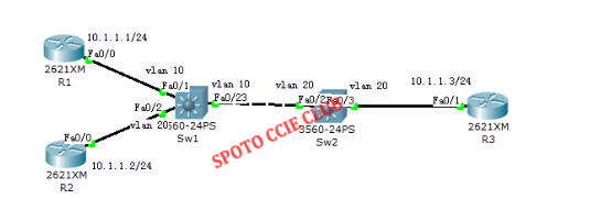
Note: When sending a packet from R1 to 10.1.1.2, the packet enters from F0 / 1 on SW1. Because F0 / 1 belongs to VLAN 10 and F0 / 2 belongs to VLAN 20, SW1 does not go to 10.1. 1.2 packets sent from the interface F0 / 2, so R1 to R2 communication failed.
When sending a packet from R1 to 10.1.1.3, the packet enters from F0 / 1 of SW1. Since F0 / 1 belongs to VLAN 10 and F0 / 23 also belongs to VLAN 10, SW1 sends the packet to 10.1.1.3 Sent from the interface F0 / 23, when SW2 from F0 / 23 received the packet, because there is no VLAN tag, so that the packet belongs to VLAN 20, it will send the packet from F0 / 3, R3 finally received the data After the packet is returned to R1, finally, although R1 and R3 belong to different VLANs, because the access interface does not have a VLAN tag, the switch does not consider it a different VLAN. Therefore, communication between R1 and R3 is successful.
3, experimental steps:
Configure router R1 R1 (config) #int fa0 / 0
R1 (config-if) #ip add 10.1.1.1 255.255.255.0
R1 (config-if) #no shut Configure router R2
R2 (config) #int fa0 / 0
R2 (config-if) #ip add 10.1.1.2 255.255.255.0
R2 (config-if) #no shut Configure router R3
R3 (config) #int fa0 / 1
R3 (config-if) #ip add 10.1.1.3 255.255.255.0
R3 (config-if) #no shut Configure switch sw1
sw1 (config) # vlan 10 Create vlan 10
sw1 (config) #vlan 20 Create vlan 20
sw1 (config) #int fa0 / 1
sw1 (config-if) #switchport mode access
sw1 (config-if) #switchport access vlan 10
sw1 (config) #int fa0 / 2
sw1 (config-if) #switchport mode access
sw1 (config-if) #switchport access vlan 20
sw1 (config) #int fa0 / 23
sw1 (config-if) #switchport mode access
sw1 (config-if) #switchport access vlan 10 Configure the switch
sw2 sw2 (config) #vlan 20
sw2 (config) #int fa0 / 23
sw2 (config-if) #switchport mode access
sw2 (config-if) #switchport access vlan 20
sw2 (config) #int fa0 / 3
sw2 (config-if) #switchport mode access s
w2 (config-if) #switchport access vlan 20
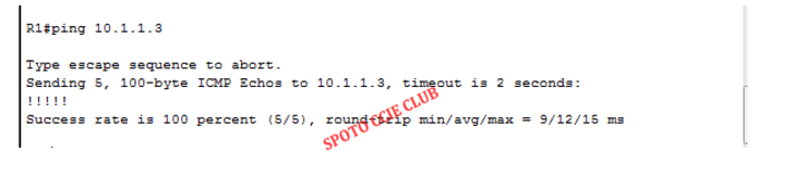
Experimental debugging: R1 R1 R3, as shown below
Experiment two Trunk configuration experiment
1, the purpose of the experiment
1) understand the communication between different VLANs. 2) The correct configuration of the trunk link. 3) R2 can not ping R1.
2, the experimental topology is as follows
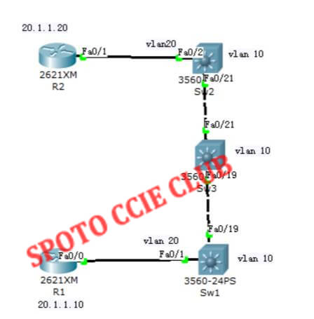
Note: This experiment shows that when a VLAN on one switch communicates with the same VLAN on another switch, if there is a switch in the middle, when no VLAN is configured on the intermediate switch, and no matter whether the trunk allows the VLAN to pass , Switch traffic on both sides can not communicate through this VLAN. Note: although SW1 and SW2 have VLAN 20, VLAN 20 communication between SW1 and SW2 needs to cross SW3, but SW3 does not have VLAN 20. Therefore, when SW3 does not have VLAN 20 itself Under, does not allow the flow of VLAN 20 through their own, so SW1 VLAN 20 to SW2 VLAN 20 unreasonable.
NOTE: Although both R1 and R2 belong to VLAN 20, both SW1 and SW2 have VLAN 20, but SW3 does not have VLAN 20. Therefore, SW3 does not allow VLAN 20 traffic to pass itself without VLAN 20 R1 to R2 barrier.
3, experimental steps to configure the router R1 R1 (config) # int fa0 / 0
R1 (config-if) #ip add 20.1.1.10 255.255.255.0
R1 (config-if) #no shut Configure the router
R2 R2 (config) #int fa0 / 1
R2 (config-if) #ip add 20.1.1.20 255.255.255.0
R2 (config-if) #no shut Configure switch sw1
sw1 (config) #vlan 10
sw1 (config) #vlan 20
sw1 (config) #int fa0 / 1
sw1 (config-if) #switchport mode access
sw1 (config-if) #switchport access vlan 20
sw1 (config) #int fa0 / 19
sw1 (config-if) #switchport trunk encapsulation dot1q
sw1 (config-if) #switchport mode trunk Configure the switch
sw2 sw2 (config) #vlan 10
sw2 (config) #vlan 20
sw2 (config) #int fa0 / 21
sw2 (config-if) #switchport trunk encapsulation dot1q
sw2 (config-if) #switchport mode trunk
sw2 (config) #int fa0 / 2
sw2 (config-if) #switchport mode access
sw2 (config-if) #switchport access vlan 20 switch sw3 sw3 (config) #vlan 10
sw3 (config) #int fa0 / 19
sw3 (config-if) #switchport trunk encapsulation dot1q
sw3 (config-if) #switchport mode trunk
sw3 (config) #int fa0 / 21
sw3 (config-if) #switchport trunk encapsulation dot1q
sw3 (config-if) #switchport mode trunk
sw3 (config) #no vlan 20 (because all switches by default their own vtp server, sw3 will be dynamically learned vlan 20, so the implementation of the order in sw3) Experimental Debugging: R2 R2 R1, as shown below
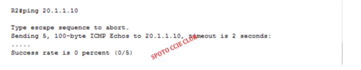
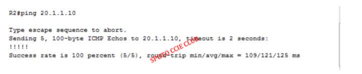
Solve the communication between R2 and R1: Because SW1 and SW2 in the middle of the switch SW3 no VLAN 20, so through the SW3 VLAN 20 traffic can not pass, the solution is to create a VLAN 20 on SW3 can be.
Create VLAN 20 on SW3 sw3 (config) #vlan 20
Experimental debugging, R2 ping R1, as shown below