
 Join Telegram Study Group ▷


The Spanning Tree Protocol is a Layer 2 management protocol that eliminates the network's Layer 2 loop by selectively blocking network redundant links, and has the link backup function.
Since the spanning tree protocol itself is relatively small, it is not as well known as routing protocols. However, it is in charge of the port forwarding power, especially when running with other protocols, the spanning tree may break the message path of other protocols, causing all kinds of strange phenomena.
Spanning Tree Protocol, like other protocols, is constantly being updated as the network continues to evolve. The "spanning tree protocol" in the title of this article is a generalized concept. It does not specifically refer to the STP protocol defined in IEEE 802.1D, but includes STP and various spanning tree protocols that have been improved on the basis of STP.
In the development of the spanning tree protocol, old defects are constantly being overcome, and new features are constantly being developed. According to the improvement of the large function point, we can roughly divide the development process of the spanning tree protocol into three generations.
The first generation of spanning tree protocol
STP/RSTP
In the early days of network development, transparent bridges were an important role that had to be mentioned. It is much smarter than a hub that only amplifies and broadcasts signals. It will quietly record the source MAC address and port number of the data frame sent to it. The next time the packet that encounters the destination MAC address is sent from the port number in the record, unless the destination MAC address is not recorded, or the destination MAC address itself is a multicast address to be sent to all ports. Through the transparent bridge, different LANs can be interoperable, the range of network operation can be expanded, and because the transparent bridge has the MAC address learning function, it will not cause the network packet collision like the Hub.
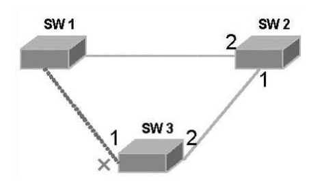
Figure 1 Schematic diagram of the spanning tree work process
The basic idea of the STP protocol is very simple. As we all know, trees growing in nature do not have loops. If the network can grow like a tree, there will be no loops. Therefore, the concepts of the root bridge, the root port, the designated port, and the path cost are defined in the STP protocol. The purpose is to cut the redundant loop by constructing a natural tree. The purpose is to achieve both link backup and path optimization. The algorithm used to construct this tree is called the spanning tree algorithm SPA.
In order to realize these functions, some information must be exchanged between the bridges. These information exchange units are called BPDUs (BridgeProtocol Data Unit). The STP BPDU is a Layer 2 packet. The destination MAC address is the multicast address 01-80-C2-00-00-00. All the bridges that support the STP protocol receive and process the received BPDUs. The data area of the message carries all the useful information for spanning tree calculation.
It is not difficult to understand the working process of the spanning tree protocol. First, the election of the root bridge is carried out. The election is based on the bridge ID of the bridge priority and the bridge MAC address. The bridge with the smallest bridge ID will become the root bridge in the network. In the network shown in Figure 1, each bridge is started with the default configuration. In the case that the bridge priorities are the same (the default priority is 32768), the bridge with the smallest MAC address becomes the root bridge, for example, in Figure 1. SW1, the role of all its ports becomes the designated port and enters the forwarding state.
Next, the other bridges will each choose a "thickest" branch as the path to the root bridge, and the role of the corresponding port becomes the root port. Assume that the link between SW2 and SW2 and SW3 in Figure 1 is a Gigabit GE link, the link between SW1 and SW3 is a 100M FE link, and the default value of the path cost of SW3 from port 1 to the root bridge is 19, and the path overhead from port 2 through SW2 to the root bridge is 4+4=8, so port 2 becomes the root port and enters the forwarding state. Similarly, port 2 of SW2 becomes the root port, and port 1 becomes the designated port and enters the forwarding state.
After the root bridge and the root port are both determined, a tree is generated, as shown by the solid line in the figure. The task below is to crop redundant loops. This work is done by blocking the corresponding port on the non-root bridge. For example, the role of port 1 of SW3 becomes a disabled port and enters the blocking state (indicated by "x" in the figure).
After the spanning tree has stabilized for a period of time (the default is about 30 seconds), all ports either enter the forwarding state or enter the blocking state. STPBPDUs are also periodically sent out from designated ports on each bridge to maintain the state of the link. If the network topology changes, the spanning tree is recalculated and the port state changes.
Of course, the Spanning Tree Protocol has a lot of content, and it is impossible to introduce them here. The reason why it takes so many inks to introduce the basic principle of spanning tree is that it is too "basic". Other various improved spanning tree protocols are based on this, and the basic ideas and concepts are similar.
The STP protocol brings a new life to the transparent bridge. However, with the deepening of applications and the development of network technology, its shortcomings have also been exposed in applications. The defects of the STP protocol are manifested in the convergence speed.
When the topology changes, the new configuration message can be propagated to the entire network after a certain delay. This delay is called Forward Delay. The default value of the protocol is 15 seconds. Before all bridges receive this change message, there may be a temporary loop if the forwarding port in the old topology has not found itself to stop forwarding in the new topology. To solve the problem of the temporary loop, the spanning tree uses a timer policy, that is, an intermediate state in which the port learns from the blocked state to the forwarding state and only learns the MAC address but does not participate in the forwarding. Both are Forward Delay, which ensures that there will be no temporary loops when the topology changes. However, this seemingly good solution actually brings at least twice the convergence time of the Forward Delay!
In order to solve this shortcoming of the STP protocol, IEEE introduced the 802.1w standard at the beginning of the century as a supplement to the 802.1D standard. The Rapid Spanning Tree Protocol (RSTP) is defined in the IEEE 802.1w standard. The RSTP protocol has made three important improvements on the basis of the STP protocol, making the convergence much faster (up to 1 second).
The first improvement: the replacement port and backup port roles for fast switching are set for the root port and the designated port. When the root port/designated port fails, the replacement port/backup port enters the forwarding state without delay. In Figure 2, all bridges run the RSTP protocol, and SW1 is the root bridge. Assume that port 1 of SW2 is the root port. Port 2 will be able to identify this topology and become the replacement port of the root port and enter the blocking state. When the link where port 1 is located fails, port 2 can immediately enter the forwarding state without waiting for twice the Forward Delay time.
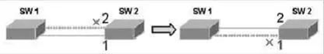
Figure 2 Schematic diagram of fast switching of RSTP redundant links
The second improvement: In a point-to-point link where only two switching ports are connected, the designated port can enter the forwarding state without delay only by performing a handshake with the downstream bridge. If three shared links are connected to the bridge, the downstream bridge will not respond to the handshake request from the upstream designated port. It can only wait for twice the Forward Delay time to enter the forwarding state.
The third improvement: the port directly connected to the terminal instead of the other bridge is defined as the Edge Port. The edge port can go directly to the forwarding state without any delay. Since the bridge cannot know whether the port is directly connected to the terminal, manual configuration is required.
It can be seen that the RSTP protocol has improved a lot compared to the STP protocol. In order to support these improvements, the BPDU format has been modified, but the RSTP protocol is still backward compatible with the STP protocol and can be mixed. Even so, RSTP and STP belong to the same single spanning tree (SST), which has its own many defects, in three aspects.
The first defect: Since the entire switching network has only one spanning tree, when the network size is large, it will lead to a long convergence time, and the influence of topology changes is also large.
The second defect: IEEE802.1Q has become popular in recent years and has gradually become the standard protocol for switches. In the case of a symmetrical network structure, a single spanning tree is not a problem. However, when the network structure is asymmetrical, a single spanning tree will affect the connectivity of the network.

Figure 3 Schematic diagram of an asymmetric network
In Figure 3, it is assumed that SW1 is the root bridge, the solid link is VLAN 10, and the dotted link is the 802.1Q trunk link, trunk VLAN 10 and VLAN 20. When the trunk port of SW2 is blocked, it is obvious that the path of VLAN 20 between SW1 and SW2 is cut off.
The third defect: when the link is blocked, it will not carry any traffic, resulting in a huge waste of bandwidth, which is more obvious in the case of a ring-shaped metropolitan area network.
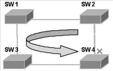
Figure 4 Schematic diagram of low SST bandwidth utilization
In Fig. 4, it is assumed that SW1 is the root bridge, and one port of SW4 is blocked. In this case, the fiber laid between SW2 and SW4 will not carry any traffic, and all traffic between SW2 and SW4 will be forwarded through SW1 and SW3, which increases the burden on several other links. These defects are not overcome by the single spanning tree SST, so multiple spanning tree protocols supporting VLANs have emerged.