

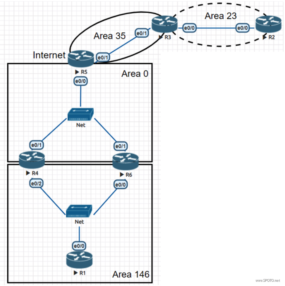
design topology
IP address planning
• The IP address segment in the topology uses 172.8.AB.X / 24:
Where AB is the combination of the two router numbers, for example, AB between R2-R3 is 23, and X is the router number, for example, X for R3 is 3
• The network segment between R1 / R4 / R6 is 172.8.146.X / 24, where X is the router number.
• The network segment between R4 / R5 / R6 is 172.8.100.X / 24, where X is the router number.
• All routers have a Loopback 0 interface and the address format is X.X.X.X / 32, where X is the router number.
Get SPOTO 100% pass dump to ace Cisco Exam in the first try!

Experimental requirements
1. It is required to configure an OSPF network according to the following standards.
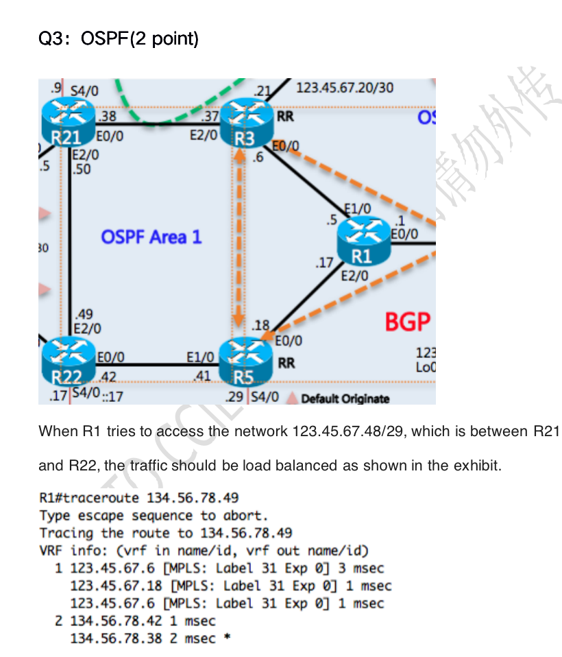
2. Configure an IP network. The experimental logic diagram is shown in the figure. The IP address is determined by the IP address planning section.
3. The routing protocol uses OSPF, the process ID is 89, and the RID is the Loopback0 address.
4. The OSPF network type of the three site links connected to R4 / R5 / R6 is configured as broadcast. The R5 router acts as a permanent DR.
5. Configure the OSPF area as shown. The area between R1 / R4 / R6 must be configured as a complete stub area.
6. R2 is a newly incorporated site, which was temporarily merged into R3 due to too late wiring construction. The area is AREA 23, and the configuration makes all networks reachable (using ping test).
7. The OSPF internal network wants to access the Internet through the R5 router, and configure R5 to meet the requirements (only consider the implementation of routing on the internal router)
8. AREA 0 is configured with MD5 authentication for security reasons, password: SPOTO
9. In AREA 146, configure R1 as the designated router and maintain a two-way neighbor relationship between R4 and R6.
10. In order to reduce network traffic, the areas where R1 is located are aggregated into the main network and advertised.
11. Due to the better link quality between R6 and R5, the proper configuration makes R1 preferentially select R6 to access external networks except for its own area.
12. Enable OSPF clear text authentication in all areas except AREA 0, password: SPOTO
Case configuration ideas and test results
- It is required to configure an OSPF network according to the following standards. (slightly)
- Configure an IP network. The experimental logic diagram is shown in the figure. The IP address is determined by the IP address planning section. (slightly)
- The routing protocol uses OSPF, the process ID is 89, and the RID is the loopback0 address. (slightly)
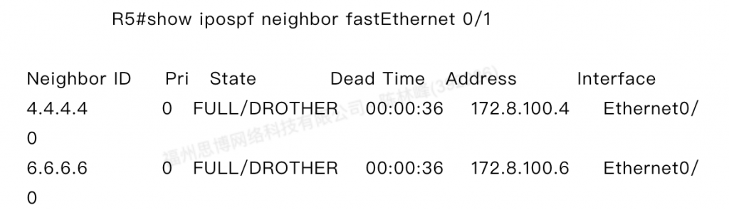
- The OSPF network type of the three site links connected to R4 / R5 / R6 is configured as broadcast. The R5 router acts as a permanent DR.
In Ethernet, the default network type is broadcast. To make R5 a DR permanently, you need to change the priority of the interfaces of R4 and R6 to 0. They are not allowed to participate in the election.
R4:
interface Ethernet0/1
IP OSPF priority 0
R6:
interface Ethernet0/1
IP OSPF priority 0
Output Check
5. Configure the OSPF area as shown. The area between R1 / R4 / R6 must be configured as a complete stub area.
R4:
router OSPF 89
area 146 stub no-summary
R6:
router OSPF 89
area 146 stub no-summary
R1:
router OSPF 89
area 146 stub
6.R2 is a newly incorporated site. Due to the delay in wiring construction, it was temporarily merged into R3. The area is AREA23. Configure to make all networks reachable (using ping test).
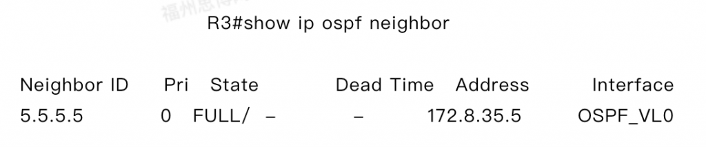
Because AREA 23 is not connected to AREA 0, it needs to be completed using a virtual link.
R3:
router OSPF 89
area 35 virtual-link 5.5.5.5
R5:
router OSPF 89
area 35 virtual-link 3.3.3.3
Output Check
7. The internal network of OSPF hopes to access the Internet through the R5 router, configure R5 to meet the requirements, and only consider the implementation of routing on the internal router.
R5:
router OSPF 89
default-information originate always
8.AREA 0 configured for MD5 authentication for security reasons, password: SPOTO
R5:
router ospf 89
area 0 authentication message-digest
area 35 virtual-link 3.3.3.3 message-digest-key 1 md5 SPOTO
interface Ethernet0/0
ip ospf message-digest-key 1 md5 SPOTO
R3:
router ospf 89
area 0 authentication message-digest
area 35 virtual-link 5.5.5.5 message-digest-key 1 md5 SPOTO
R4:
router ospf 89
area 0 authentication message-digest
interface Ethernet0/1
ip ospf message-digest-key 1 md5 SPOTO
R6:
router ospf 89
area 0 authentication message-digest
interface Ethernet0/1
ip ospf message-digest-key 1 md5 SPOTO
9.In Area 146, configure R1 as the designated router and maintain a two-way neighbor relationship between R4 and R6.
R4:
interface Ethernet0/2
IP OSPF priority 0
R6:
interface Ethernet0/0
IP OSPF priority 0
10. In order to reduce network traffic, the areas where R1 is located are aggregated into the main network and advertised.
R4、R6:
router OSPF 89
area 146 range 172.8.0.0 255.255.0.0
11. Because the link quality between R6 and R5 is good, the proper configuration makes R1 preferentially select R6 to access external networks except for its own area.
R4:
router OSPF 89
area 146 default-cost 100
12.Enable OSPF clear text authentication in all areas except AREA 0, password: SPOTO
R1:
router OSPF 89
area 146 authentication
interface Ethernet0/0
IP OSPF authentication-key SPOTO
R4:
router OSPF 89
area 146 authentication
interface Ethernet0/2
IP OSPF authentication-key SPOTO
R6:
router OSPF 89
area 146 authentication
interface Ethernet0/0
IP OSPF authentication-key SPOTO
R5:
router OSPF 89
area 35 authentication
interface Ethernet1/0
IP OSPF authentication-key SPOTO
R3:
router OSPF 89
area 23 authentication
area 35 authentication
interface Ethernet1/0
IP OSPF authentication-key SPOTO
interface Ethernet0/0
IP OSPF authentication-key SPOTO
R2:
router OSPF 89
area 23 authentication
interface Ethernet0/0
IP OSPF authentication-key SPOTO
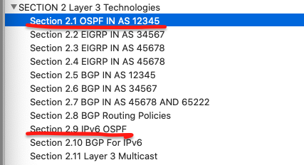
OSPF is currently the most widely used protocol, and it is also very important in the CCIE exam. The following picture is the directory of the configuration part in the Cisco CCIE LAB exam. We can see that there are two chapters in section 2 that are related to OSPF. There is also an OSPF question in the troubleshooting part, so it is necessary to understand OSPF. There are many OSPF labs in our group. If you want to do more experiments, please consult us
Configuration
Troubleshooting part
Related reading:
Comments