


This is the best labs to learn BGP
Autonomous system AS, AS refers to a series of routers under unified technical management. For example, a network running OSPF or a network running ISIS can be used as an AS. EGP runs at the borders of ASs to exchange routing information between ASs. With EGP, each AS can independently select its own suitable IGP protocol and obtain routing information of other ASs through EGP. BGP is an inter-domain routing protocol that provides loop-free routing between autonomous systems.
If you want to know more info about BGP configuration and better Pass the lab exam, contact us for 100% real exam study materials and professional help!

This is the best labs to learn BGP
Table of Contents
Experimental topology
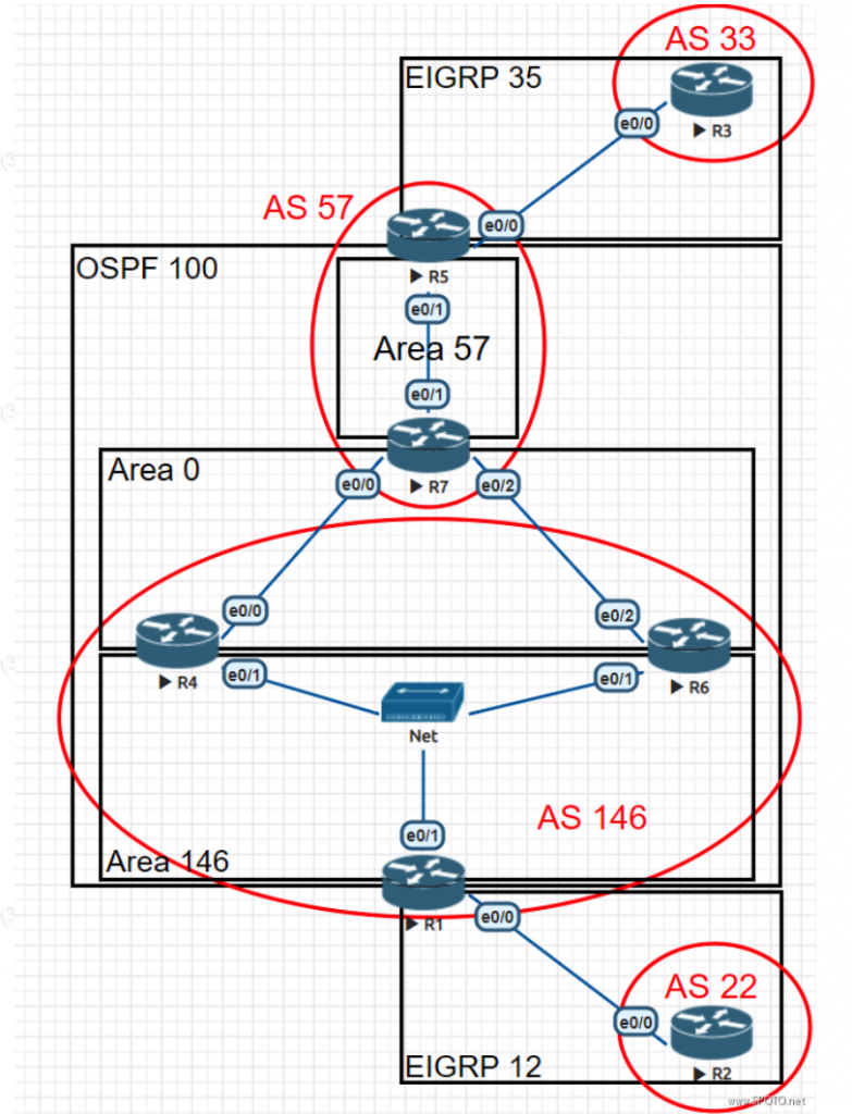
IP address planning
1. The IP address segment in the topology is: 172.8.AB.X / 24, where AB is a combination of two router numbers.
2. For example: AB between R3-R5 is 35, and X is the router number, for example, X = 3 for R3
3. All routers have a Loopback 0 interface, the address format is: X.X.X.X / 32, where X is the router number.
4. The network segment between R1 / R4 / R6 is: 172.8.146.X / 24, where X is the router number.
5. There are no special requirements, and static routes are not allowed.
Experimental requirements
• IGP section:
1. Configure the OSPF area as shown in the figure. The RID is the Loopback 0 address. Area 146 should be configured as a special area of OSPF.
2. Configure other routing protocols, and redistribute them so that routes can be injected into each other to achieve network-wide interworking.
3. Configure policy routing for R1 so that the data flow from R2 to Area 57 via R1 goes to R6; the data flow from R2 to EIGRP 35 via R1 goes to R4.
(Please use Traceroute for 3.3.3.3 and 5.5.5.5 in R2)
4. Add the following network segments to EIGRP 35 on R3:
Loopback17: 17.17.17.17/32, Loopback101: 100.100.100.101/32
Loopback18: 18.18.18.18/32, Loopback102: 100.100.100.102/32
a. Configure the loopback 18 network segment to be transmitted only within EIGRP 35, and other addresses require the entire network to ping through.
b. Configure the most accurate route summary for Loopback 100 and Loopback 101, hide detailed routes, and summary routes are not allowed to appear in EIGRP 35.
• BGP part:
1. Configure BGP according to the plan in red font as shown in the figure. The RID is the Loopback 0 address.
2. Configure R1 of AS 146 as a route reflector and R4 / R6 as clients. Requires peer-group configuration.
3. Add the following network segments to R2 and publish them to BGP:
Loopback24: 192.168.24.1/24 Loopback25: 192.168.25.1/24 Loopback26: 192.168.26.1/24
Add the following network segment on R3, Loopback30: 30.30.30.30/27, and publish it to BGP:
Configure the R2 BGP table as follows:
4. Modify the BGP routing attributes on the appropriate routers so that the path from R2 to 30.30.30.30/27 is: R1-R6-R7-R5-R3.
At this time, the BGP table of R2 remains unchanged as shown above, and the BGP routing of the R4 router is not changed.
Case configuration ideas and test results•
IGP section:
- 1. Configure the OSPF area as shown in the figure. The RID is the Loopback 0 address. Area 146 should be configured as a special area of OSPF.
- 2. Configure other routing protocols, and redistribute them so that routes can be injected into each other to achieve network-wide interworking.
Configure the interface:
R1:
- interface Loopback0
- ip address 1.1.1.1 255.255.255.255
- no shutdown
- interface Ethernet0/0
- ip address 172.8.12.1 255.255.255.0
- no shutdown
- interface Ethernet0/1
- ip address 172.8.146.1 255.255.255.0
- no shutdown
- R2:
- interface Loopback0
- ip address 2.2.2.2 255.255.255.255
- no shutdown
- interface Ethernet0/0
- ip address 172.8.12.2 255.255.255.0
- no shutdown
R3:
- interface Loopback0
- ip address 3.3.3.3 255.255.255.255
- no shutdown
- interface Ethernet0/0
- ip address 172.8.35.3 255.255.255.0
- no shutdown
R4:
- interface Loopback0
- ip address 4.4.4.4 255.255.255.255
- no shutdown
- interface Ethernet0/1
- ip address 172.8.146.4 255.255.255.0
- no shutdown
- interface Ethernet0/0
- ip address 172.8.47.4 255.255.255.0
- no shutdown
R5:
- interface Loopback0
- ip address 5.5.5.5 255.255.255.255
- no shutdown
- interface Ethernet0/0
- ip address 172.8.35.5 255.255.255.0
- no shutdown
- interface Ethernet0/1
- ip address 172.8.57.5 255.255.255.0
- no shutdown
R6:
- interface Loopback0
- ip address 6.6.6.6 255.255.255.255
- no shutdown
- interface Ethernet0/1
- ip address 172.8.146.6 255.255.255.0
- no shutdown
- interface Ethernet0/2
- ip address 172.8.67.6 255.255.255.0
- no shutdown
R7:
- interface Loopback0
- ip address 7.7.7.7 255.255.255.255
- no shutdown
- interface Ethernet0/0
- ip address 172.8.47.7 255.255.255.0
- no shutdown
- interface Ethernet0/1
- ip address 172.8.57.7 255.255.255.0
- no shutdown
- interface Ethernet0/2
- ip address 172.8.67.7 255.255.255.0
- no shutdown
Configure the routing protocol:
R1:
- router ospf 100
- router-id 1.1.1.1
- network 1.1.1.1 0.0.0.0 area 146
- network 172.8.146.1 0.0.0.0 area 146
- area 146 nssa
- router eigrp 12
- network 172.8.12.1 0.0.0.0
R2:
- router eigrp 12
- network 2.2.2.2 0.0.0.0
- network 172.8.12.2 0.0.0.0
R3:
- router eigrp 35
- network 3.3.3.3 0.0.0.0
- network 172.8.35.3 0.0.0.0
R4:
- router ospf 100
- router-id 4.4.4.4
- network 4.4.4.4 0.0.0.0 area 0
- network 172.8.47.4 0.0.0.0 area 0
- network 172.8.146.4 0.0.0.0 area 146
- area 146 nssa default-information-originate // Configure as NSSA and manually delegate the default route
orarea 146 nssa no-summary // Configured as Totally NSSA will automatically delegate the default route
R5:
- router ospf 100
- router-id 5.5.5.5
- network 5.5.5.5 0.0.0.0 area 57
- network 172.8.57.5 0.0.0.0 area 57
- router eigrp 35
- network 172.8.35.5 0.0.0.0
R6:
- router ospf 100
- router-id 6.6.6.6
- network 6.6.6.6 0.0.0.0 area 0
- network 172.8.67.6 0.0.0.0 area 0
- network 172.8.146.6 0.0.0.0 area 146
- area 146 nssa default-information-originate // Configure as NSSA and manually delegate the default route
- or
- area 146 nssa no-summary // Configured as Totally NSSA will automatically delegate the default route
R7:
- router ospf 100
- router-id 7.7.7.7
- network 7.7.7.7 0.0.0.0 area 0
- network 172.8.47.7 0.0.0.0 area 0
- network 172.8.57.7 0.0.0.0 area 57
- network 172.8.67.7 0.0.0.0 area 0
Redistribution routes:
R1:
- router eigrp 12
- redistribute ospf 100 metric 10000 100 255 1 1500
- router ospf 100
- redistribute eigrp 12 subnets
R5:
- router eigrp 35
- redistribute ospf 100 metric 10000 100 255 1 1500
- router ospf 100
- redistribute eigrp 35 subnets
Note:
If Area 146 uses Totally NSSA, R1 cannot learn the fine route of Loopback 0 address of R4 and R6, but it can be reached by default route, so R1, R4, and R6 can establish iBGP neighbors (provided that R4 and R6 can learn the loopback of R1 0 address fine routing). If both are accessed through the default route, a neighbor cannot be established. Or you can notify Loopback 0 of R4 and R6 into Area 146.
If Area 146 adopts NSSA but does not manually decentralize the default route, it will cause R2 to fail to learn the default route through redistribution, which will affect the realization of other requirements.
3. Configure policy routing for R1 so that the data flow from R2 to Area 57 via R1 goes to R6; the data flow from R2 to EIGRP 35 via R1 goes to R4.
(Please use Traceroute for 5.5.5.5 and 3.3.3.3 in R2)
R1:
- access-list 100 permit ip any host 5.5.5.5
- access-list 100 permit ip any 172.8.57.0 0.0.0.255
- access-list 101 permit ip any host 3.3.3.3
- access-list 101 permit ip any 172.8.35.0 0.0.0.255
- route-map PBR permit 10
- match ip address 100
- set ip next-hop 172.8.146.6
- route-map PBR permit 20
- match ip address 101
- set ip next-hop 172.8.146.4
- route-map PBR permit 30
- interface Ethernet0/0
- ip policy route-map PBR
- verification:
R2#traceroute 5.5.5.5
- Type escape sequence to abort.
- Tracing the route to 5.5.5.5
- VRF info: (vrf in name/id, vrf out name/id)
- 1 172.8.12.1 0 msec 0 msec 0 msec
- 2 172.8.146.6 1 msec 1 msec 1 msec
- 3 172.8.67.7 1 msec 1 msec 0 msec
- 4 172.8.57.5 1 msec * 2 msec
R2#traceroute 3.3.3.3
- Type escape sequence to abort.
- Tracing the route to 3.3.3.3
- VRF info: (vrf in name/id, vrf out name/id)
- 1 172.8.12.1 0 msec 1 msec 1 msec
- 2 172.8.146.4 2 msec 1 msec 0 msec
- 3 172.8.47.7 1 msec 2 msec 1 msec
- 4 172.8.57.5 2 msec 1 msec 1 msec
- 5 172.8.35.3 2 msec * 4 msec
Note:
Although there are no routes for 3.3.3.3 and 172.8.35.0 on R2 (Area 146 is a special area), the default route can be used for communication.
4. Add the following network segments to EIGRP 35 on R3:
Loopback17: 17.17.17.17/32, Loopback101: 100.100.100.101/32
Loopback18: 18.18.18.18/32, Loopback102: 100.100.100.102/32
a. Configure the loopback 18 network segment to be transmitted only within EIGRP 35. Other addresses must be pinged through the entire network.
b. Configure the most accurate route summary for Loopback 100 and Loopback 101, hide detailed routes, and summary routes are not allowed to appear in EIGRP 35.
R3:
- interface Loopback 17
- ip address 17.17.17.17 255.255.255.255
- no shutdown
- interface Loopback 18
- ip address 18.18.18.18 255.255.255.255
- no shutdown
- interface Loopback 101
- ip address 100.100.100.101 255.255.255.255
- no shutdown
- interface Loopback 102
- ip address 100.100.100.102 255.255.255.255
- no shutdown
- router eigrp 35
- network 17.17.17.17 0.0.0.0
- network 18.18.18.18 0.0.0.0
- network 100.100.100.101 0.0.0.0
- network 100.100.100.102 0.0.0.0
R5:
- ip prefix-list deny_18 seq 5 permit 18.18.18.18/32
- route-map e2o deny 10
- match ip address prefix-list deny_18
- route-map e2o permit 20
- router ospf 100
- redistribute eigrp 35 subnets route-map e2o
- summary-address 100.100.100.100 255.255.255.252
- ip prefix-list deny_100 seq 5 permit 100.100.100.100/30
- route-map o2e deny 10
- match ip address prefix-list deny_100
- route-map o2e permit 20
- router eigrp 35
- redistribute ospf 100 metric 10000 100 255 1 1500 route-map o2e
• BGP part:
1. Configure BGP according to the plan in red font as shown in the figure. The RID is the Loopback 0 address.
2. Configure R1 of AS 146 as a route reflector and R4 / R6 as clients. Requires peer-group configuration.
R1:
- router bgp 146
- bgp router-id 1.1.1.1
- neighbor peer peer-group
- neighbor peer remote-as 146
- neighbor peer update-source Loopback0
- neighbor peer route-reflector-client
- neighbor peer next-hop-self
- neighbor 4.4.4.4 peer-group peer
- neighbor 6.6.6.6 peer-group peer
- neighbor 172.8.12.2 remote-as 22
R2:
- router bgp 22
- bgp router-id 2.2.2.2
- neighbor 172.8.12.1 remote-as 146
R3:
- router bgp 33
- bgp router-id 3.3.3.3
- neighbor 172.8.35.5 remote-as 57
R4:
- router bgp 146
- bgp router-id 4.4.4.4
- neighbor 1.1.1.1 remote-as 146
- neighbor 1.1.1.1 update-source Loopback0
- neighbor 1.1.1.1 next-hop-self
- neighbor 172.8.47.7 remote-as 57
R5:
- router bgp 57
- bgp router-id 5.5.5.5
- neighbor 7.7.7.7 remote-as 57
- neighbor 7.7.7.7 update-source Loopback0
- neighbor 7.7.7.7 next-hop-self
- neighbor 172.8.35.3 remote-as 33
R6:
- router bgp 146
- bgp router-id 6.6.6.6
- neighbor 1.1.1.1 remote-as 146
- neighbor 1.1.1.1 update-source Loopback0
- neighbor 1.1.1.1 next-hop-self
- neighbor 172.8.67.7 remote-as 57
R7:
- router bgp 57
- bgp router-id 7.7.7.7
- neighbor 5.5.5.5 remote-as 57
- neighbor 5.5.5.5 update-source Loopback0
- neighbor 5.5.5.5 next-hop-self
- neighbor 172.8.47.4 remote-as 146
- neighbor 172.8.67.6 remote-as 146
1. Add the following network segments to R2 and publish them to BGP:
Loopback24: 192.168.24.1/24 Loopback25: 192.168.25.1/24 Loopback26: 192.168.26.1/24
Add the following network segment on R3, Loopback30: 30.30.30.30/27, and publish it to BGP:
Configure the R2 BGP table as follows:
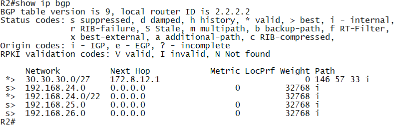
R2:
- interface Loopback 24
- ip address 192.168.24.1 255.255.255.0
- interface Loopback 25
- ip address 192.168.25.1 255.255.255.0
- interface Loopback 26
- ip address 192.168.26.1 255.255.255.0
- router bgp 22
- network 192.168.24.0 mask 255.255.255.0
- network 192.168.25.0 mask 255.255.255.0
- network 192.168.26.0 mask 255.255.255.0
- aggregate-address 192.168.24.0 255.255.252.0 summary-only
R3:
- interface Loopback30
- ip address 30.30.30.30 255.255.255.224
- router bgp 33
- network 30.30.30.0 mask 255.255.255.224
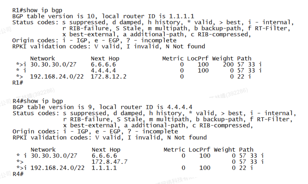
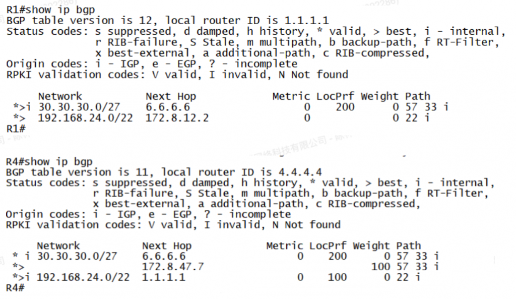
4. Modify the BGP routing attributes on the appropriate routers so that the path from R2 to 30.30.30.30/27 is: R1-R6-R7-R5-R3.
At this time, the BGP table of R2 remains unchanged as shown above, and the BGP routing of the R4 router is not changed.
Solution 1:
R1:
- access-list 1 permit 30.30.30.0 0.0.0.31
- route-map x permit 10
- match ip address 1
- set weight 200
- route-map x permit 20
- router bgp 146
- neighbor 6.6.6.6 route-map x in
- clear ip bgp * soft
Solution 2:
R6:
- access-list 1 permit 30.30.30.0 0.0.0.31
- route-map x permit 10
- match ip address 1
- set local-preference 200
- route-map x permit 20
- router bgp 146
- neighbor 172.8.67.7 route-map x in
- clear ip bgp * soft
R4:
- router bgp 146
- neighbor 172.8.47.7 weight 100
- clear ip bgp * soft
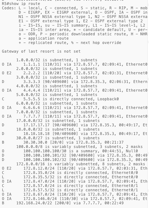
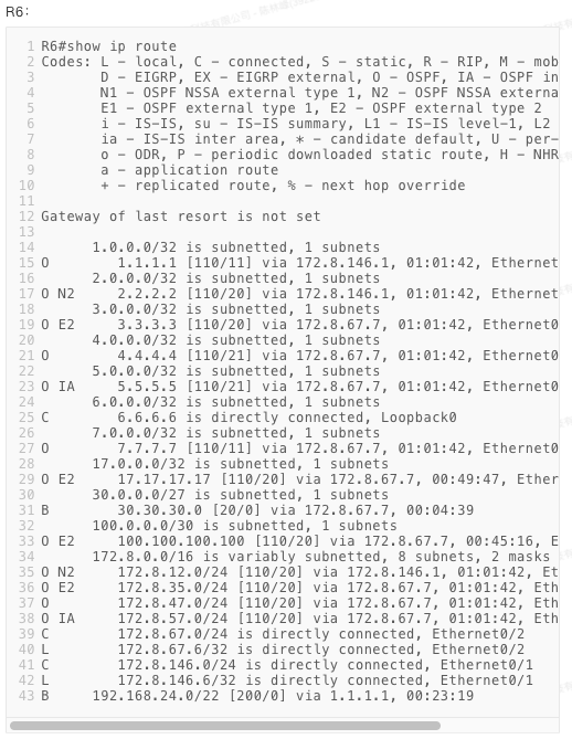
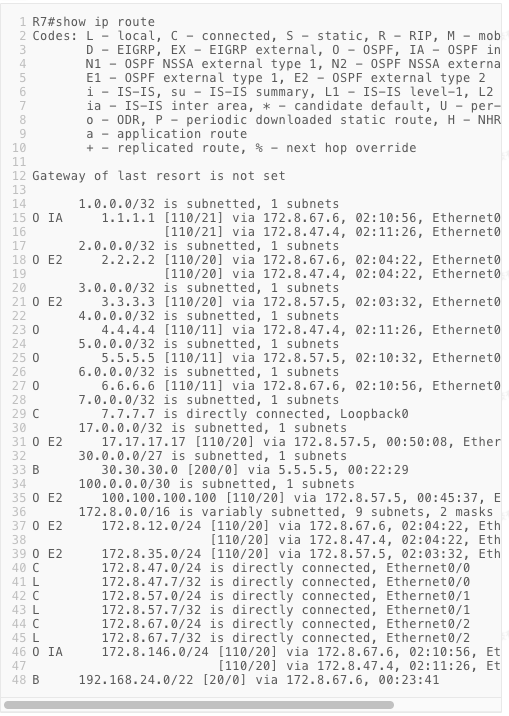
Summary of routing table:
If you want more labs and help, consult SPOTO for more info.

Read more:
Comments