


When a website or application is hosted on multiple servers, a load balancer helps distribute incoming requests so that no single server gets overwhelmed. The F5 BIG-IP is a popular load balancer device that sits between the users (clients) and a group of servers. It acts as a traffic proxy: clients send requests to the BIG-IP’s address, and the BIG-IP forwards each request to one of the backend servers in a way that spreads out the load. This ensures the application can handle more users and stay reliable even during peak traffic.
Key Components
- Client (User): The end-user’s device or browser that sends a request for a website or application. In the diagram, this is represented by a user icon on the left.
- BIG-IP Load Balancer: The F5 device that receives incoming client requests and redirects them to one of the servers in the backend pool. It has a special listening point called a Virtual Server.
- Virtual Server (frontend IP): This is not an actual physical server, but a virtual IP address/port on the BIG-IP that clients connect to. It represents the multiple real servers as a single point of contact. For example, clients might connect to 203.0.113.10 (the virtual IP) which is hosted on the BIG-IP. The BIG-IP then knows the pool of actual servers behind it.
- Pool (Backend Servers): The group of real servers that host the application (in the diagram, Server 1, Server 2, Server 3). The BIG-IP maintains a pool of these servers and can send incoming traffic to any server in the pool. Each server has the same content, so it doesn’t matter which one handles a given request.
- Health Monitors: These are automatic check-ups or “pings” that the BIG-IP continuously sends to each server to ensure it’s healthy (alive and responding). The purpose of health monitors is to check server health and performance. If a server is not responding or is down, the BIG-IP marks it unavailable and will stop sending traffic to it. This way, users won’t be sent to a failed server.
How the Traffic Flows
- Client connects to the Virtual Server: The client (user) initiates a request (for example, loading a webpage) to the application’s public IP address. This IP is actually the Virtual Server on the F5 BIG-IP. From the client’s perspective, they are just contacting the website’s address – they do not know a load balancer is handling the traffic.
- BIG-IP receives the request: The BIG-IP device receives the incoming request on its Virtual Server (the front-end IP). At this point, the BIG-IP decides which backend server should handle the request. It has various algorithms (like round-robin, least connections, etc.), but the basic idea is to choose a server that will distribute the load evenly. For example, if Server 1 is busy, the BIG-IP might pick Server 2 for this new request.
- Request is forwarded to a server in the pool: The load balancer forwards the client’s request to the chosen server on the back end. In our diagram, suppose the BIG-IP forwards the request to Server 2. The BIG-IP acts as an intermediary – from the outside, the client is still communicating with the BIG-IP’s IP, but the actual content is coming from Server 2 on the backend.
- Server processes request and responds: Server 2 processes the request (for example, it generates the webpage data) and sends the response back to the BIG-IP load balancer. The BIG-IP then returns the response to the client. This all happens quickly and transparently. (The return path is not explicitly drawn in the diagram, but the BIG-IP does relay the server’s response back to the client over the established connection.) The client sees a successful response from the website without knowing which server produced it.
- Health monitoring (continuous): All the while, the BIG-IP is running its health monitors in the background. It might be pinging each server or sending test requests at intervals to verify they respond correctly. If, for example, Server 3 fails to respond to a health check (meaning it might be down), the BIG-IP will mark Server 3 as unhealthy and stop forwarding any new client requests to it. This ensures that users are only sent to Server 1 or Server 2 (the healthy servers) until Server 3 recovers. This health check mechanism prevents users from being routed to a broken or overloaded server.
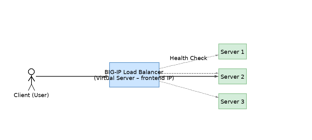
 Figure: How F5 BIG-IP Load Balancer Works to Distribute Traffic Across Servers. In this diagram, the client’s request goes to the BIG-IP (Virtual Server on the load balancer), and the BIG-IP forwards it to one of the available backend servers. Solid arrows show the flow of user traffic, and the dashed arrows labeled “Health Check” show the BIG-IP monitoring each server’s status. The BIG-IP will only send traffic to servers that are responding and healthy.
In summary, the F5 BIG-IP load balancer sits in front of the servers and acts as an “invisible facilitator” between the user and the server group. It ensures all servers are used more or less equally and can take servers out of rotation if they are faulty. This way, no single machine becomes a bottleneck and the application remains available even if one server fails, resulting in better reliability and user experience.
Comments