


Last Updated: March 2025 – This guide covers the latest F5 BIG-IP version (as of this writing, v17.xf5.com) and provides step-by-step configuration instructions for common real-world use cases. We’ll walk through Web Application Load Balancing, SSL Offloading (TLS termination), and Global Server Load Balancing (GSLB) using both the F5 GUI and the CLI (tmsh). Along the way, we’ll explain key BIG-IP concepts and include diagrams for architecture and traffic flow. This tutorial is aimed at IT professionals setting up F5 BIG-IP in production or lab environments.
Table of Contents
Understanding F5 BIG-IP: Core Concepts and Use Cases
F5 BIG-IP is a family of Application Delivery Controller (ADC) appliances and virtual devices that provide traffic management, security, and high availability for applications. The Local Traffic Manager (LTM) module of BIG-IP handles local load balancing (within a data center), while the DNS (formerly GTM) module handles global traffic across data centers. Before diving into configurations, let’s clarify a few core concepts and how they relate to our use cases:
- Node / Server: A backend system (physical or virtual) that hosts an application (identified by an IP address). In F5 terms, a Node is often the server IP address itself.
- Pool and Pool Members: A pool is a logical grouping of servers offering the same application. Each server in a pool is a pool member defined by server IP + service port. Pools allow BIG-IP to distribute client requests among multiple servers for load balancing and high availability.
- Virtual Server (VS): A virtual server is a listener on the BIG-IP that has a virtual IP (VIP) and service port (e.g. 203.0.113.10:80). Clients connect to the virtual server as if it were the service. The BIG-IP then proxies these connections to the appropriate pool member on the backendf5.comf5.com. In essence, the virtual server is the frontend address for your application on the BIG-IP.
- Profiles: Profiles are sets of configuration settings that define specific behaviors (for example, an HTTP profile for HTTP parsing, a Client SSL profile to terminate HTTPS, etc.). Attaching profiles to virtual servers enables advanced features like SSL offload, compression, etc.
- Monitors: Health monitors are configurable tests that BIG-IP uses to check the availability of pool members (e.g. an HTTP GET to “/health” on a server). If a server fails its health check, BIG-IP can dynamically remove it from the pool to avoid sending traffic to an unhealthy node.
Using these concepts, BIG-IP LTM can ensure requests are always directed to a healthy server and can scale out applications by balancing load. Now, let’s map these to our real-world scenarios:
- Web Application Load Balancing: Distributing client traffic (HTTP/HTTPS) across multiple servers in a pool to improve capacity and reliability of a web application.
- SSL Offloading (TLS Termination): Terminating HTTPS traffic on the BIG-IP (which decrypts it) and forwarding it to backend servers as HTTP. This offloads the CPU-intensive SSL/TLS processing from servers and centralizes certificate management on the BIG-IP.
- Global Server Load Balancing (GSLB): Using BIG-IP’s DNS/GTM module to distribute traffic across multiple data centers or geographic locations. GSLB directs clients to the best or closest data center by responding to DNS queries with the IP of a local virtual server in one of the data centers, based on factors like availability, load, or topology.
Each use case will be covered in the following sections with configuration steps via the GUI (Traffic Management UI) and via the CLI (tmsh). We will also include verification steps and troubleshooting tips.
Web Application Load Balancing with BIG-IP LTM
Web application load balancing is the foundational feature of F5 BIG-IP LTM. In this scenario, we have an application (say, a website) hosted on multiple servers. Our goal is to configure the BIG-IP to present a single front-end IP for the site and distribute incoming client requests across the backend servers.
Scenario: Imagine two web servers running an application on HTTP port 80. We want clients to use a single URL/IP (e.g., http://www.example.com at 198.51.100.100) and have BIG-IP spread the load between Server1 and Server2 (e.g., 10.0.0.1 and 10.0.0.2). We’ll configure a virtual server on BIG-IP listening on 198.51.100.100:80 and a pool containing the two servers on port 80.
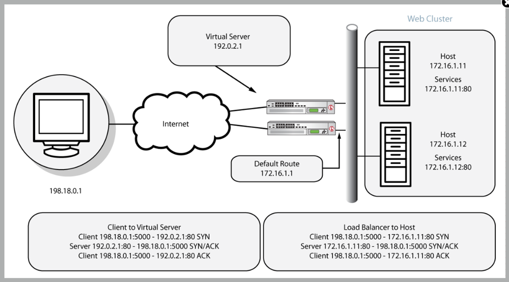
 Basic load balancing architecture: Clients connect to a BIG-IP Virtual Server (e.g., 192.0.2.1) instead of directly to the web servers. The BIG-IP LTM decides which Pool Member (172.16.1.11:80 or 172.16.1.12:80 in this example) will serve each request, and it seamlessly proxies the connection. This diagram illustrates a simple HTTP request flow: the client’s TCP connection and HTTP request terminate at the BIG-IP, which then opens a separate connection to the selected server. The servers’ responses go back to the BIG-IP, which then forwards them to the clientf5.comf5.com. From the client’s perspective, all responses come from the BIG-IP’s virtual IP.
Configuration via GUI (TMUI)
Using the F5 Configuration utility (web GUI) is a straightforward way to set up load balancing:
- Define Nodes (Servers): In the GUI, navigate to Local Traffic > Nodes > Node List > Create. Add each backend server:
- For example, create a Node for Server1 with IP address 10.0.0.1, and another for Server2 with IP 10.0.0.2. (Optionally, you can skip explicitly creating nodes; BIG-IP will auto-create node objects when adding pool members.)
- Create a Pool: Go to Local Traffic > Pools > Pool List > Create. Configure:
- Name: e.g., app_pool.
- Health Monitor: select an appropriate monitor (e.g., http). This tells BIG-IP how to verify servers are up. The default HTTP monitor sends a GET “/” request and expects an HTTP 200 OK.
- Load Balancing Method: you can leave as Round Robin (the default) to cycle through servers evenly, or choose another method (Least Connections, etc.) depending on requirements.
- Members: Add the two servers as members. Select each Node (or type the IP) and service port 80 (for HTTP). For example, add 10.0.0.1:80 and 10.0.0.2:80 as members.
- Click Finished to create the pool.
- Create a Virtual Server: Navigate to Local Traffic > Virtual Servers > Virtual Server List > Create. Configure the virtual server to be the frontend for the application:
- Name: e.g., vs_web_app.
- Destination Type: Host (since we’ll use a specific IP).
- Destination Address/Mask: 198.51.100.100/32 (the VIP that clients will use).
- Service Port: 80 (HTTP). You can select “HTTP” from the service list which sets port 80 and also auto-selects an HTTP profile.
- HTTP Profile: select http (should be default if you chose service “HTTP”). This enables HTTP protocol awareness on the virtual server.
- SNAT: if your servers are on an internal network and not routing back to the BIG-IP, set SNAT Automap (this makes the BIG-IP translate source addresses to itself, to manage return traffic). If the servers use the BIG-IP as their gateway, SNAT may not be needed. (In many cases, SNAT Automap is recommended).
- Default Pool: select app_pool (the pool you created).
- Leave other settings at default for now and click Finished.
- Review and Save: You should now see the virtual server in the list, with its address and the pool assigned. The pool should show both members and their status (green if monitors succeeded). At this point, the BIG-IP is ready to accept client connections on 198.51.100.100:80 and load balance them across the two servers.
Verification (GUI): On the BIG-IP dashboard (Statistics > Module Statistics > Local Traffic > Virtual Servers), you can watch the connection counts or use Statistics > Pools to see each pool member’s traffic. Ensure both pool members show as Available (Green) in the Local Traffic > Pools > app_pool page. If a server is down (monitor fails), it will appear as Offline (red) and BIG-IP will automatically stop sending it traffic.
Configuration via CLI (tmsh)
F5’s Traffic Management Shell (tmsh) allows accomplishing all of the above via command line. You can SSH into the BIG-IP or use the console, then enter tmsh. Here’s how to create the same objects via CLI:
- Create a pool with members: Use the
tmsh create ltm poolcommand. For example:
tmsh create ltm pool app_pool monitor http load-balancing-mode round-robin \
     members add { 10.0.0.1:80 { address 10.0.0.1 } 10.0.0.2:80 { address 10.0.0.2 } }
- This creates a pool named “app_pool” with the HTTP monitornetworkgalaxy.orgnetworkgalaxy.org and two members (10.0.0.1:80 and 10.0.0.2:80). The
load-balancing-modecan be omitted to use the default (round-robin) as well. - Create a virtual server: Use
tmsh create ltm virtual. For example:
tmsh create ltm virtual vs_web_app destination 198.51.100.100:80 \
     profiles add { http } pool app_pool snat automap
- Let’s break down this command:
- destination 198.51.100.100:80 sets the VIP and port.
- profiles add { http } attaches the HTTP profile (enabling layer7 parsing). BIG-IP has a built-in profile named “http” for this purpose.
- pool app_pool associates the virtual with the pool we created.
- snat automap enables SNAT using the BIG-IP’s self-IP, which is often needed if the servers don’t have a direct route back to the client via the BIG-IPf5.comf5.com.(Note: If you want to allow both HTTP and HTTPS on the same VIP, you would create two virtual servers – one on port 80 and one on 443 (we’ll cover 443 in SSL Offloading section). Each VS can point to the same pool but have different profiles.)
- Verify via CLI: Run
tmsh list ltm virtual vs_web_app,tmsh list ltm pool app_pool, andtmsh show ltm pool app_pool membersto verify the configuration and the health/status of members. Theshowcommand will reveal monitor status for each pool member (e.g., up/down). You can also usetmsh show ltm virtual vs_web_appto see connection stats.
Basic Connectivity Testing: After configuration, test that the virtual server is accessible. For example, from a client machine, try to curl http://198.51.100.100/ or open that URL in a browser. You should get a response from one of the backend servers. Refresh multiple times to see load balancing in action (e.g., if each server returns a slightly different content or via logs on the servers). If the virtual server is not responding, ensure:
- The virtual server status is Enabled (ENABLED). (On CLI, check
tmsh show ltm virtual vs_web_app, and ensure it is not disabled or in a forced-down state.) - Pool members show as up. If they are marked down (red), check that the servers are running and reachable by the BIG-IP, and that the health monitor settings are correct (maybe the servers require a specific HTTP request or host header for health check).
- If using SNAT, verify the BIG-IP’s self IP is allowed in server’s firewall and that return traffic is indeed flowing back via BIG-IP. If not using SNAT, ensure the server’s default gateway is the BIG-IP or it has a route to client networks via the BIG-IP.
Troubleshooting Tips: For load balancing issues, check the LTM logs on the BIG-IP (/var/log/ltm file) – it often logs pool member status changes and may log details if a pool member is marked down by a monitor. You can also use tcpdump on the BIG-IP (e.g., tcpdump -ni 0.0:nnn host 10.0.0.1 and port 80) to see if traffic is reaching your servers and responses coming back. Common mistakes include failing to enable SNAT when needed (resulting in servers responding directly to clients, which may not work if the BIG-IP is in-line) or misconfiguring VLANs/listeners so the BIG-IP isn’t actually receiving the traffic. Adjust accordingly and re-test.
SSL Offloading (TLS Termination) on BIG-IP
SSL offloading (also known as SSL termination) means the BIG-IP will handle HTTPS encryption and decryption on behalf of backend serversblog.xeynergy.com. Clients establish a secure TLS connection to the BIG-IP, and the BIG-IP then forwards the traffic to the pool members unencrypted (typically via HTTP). This reduces the load on servers (since they no longer decrypt/encrypt) and centralizes certificate management on the BIG-IP. It also enables the BIG-IP to inspect and modify HTTP traffic (for security or routing) since it sees the plaintext after decrypting.
Scenario: We will extend the previous example to support HTTPS traffic. We want the same web application to be accessible over HTTPS (443). BIG-IP will present an SSL certificate to clients and decrypt incoming requests, then send them to the servers via HTTP. The servers will only need to handle HTTP – they can even be unaware that clients are using HTTPS. Optionally, the BIG-IP can re-encrypt traffic to the servers (SSL bridging) if end-to-end encryption is required, but here we’ll focus on true offloading (client-side HTTPS only).
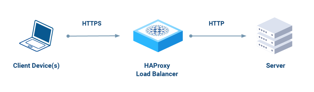
SSL Offloading (Termination) flow: In SSL offload mode, clients initiate an HTTPS connection to the BIG-IP (which holds the site’s certificate). The BIG-IP decrypts the traffic and communicates with backend servers over HTTP. Responses from servers are then encrypted by BIG-IP and sent back to the client, completing the secure transaction. This diagram illustrates that the encryption workload is handled at the load balancer, not on each server, greatly reducing CPU overhead on the servers.
Prerequisites: SSL Certificate on BIG-IP
To terminate HTTPS, the BIG-IP needs an SSL certificate and private key for the domain it will serve. In a production scenario, you’d obtain a certificate (e.g., from a Certificate Authority) for your site’s domain (e.g., www.example.com). For a lab or test, you could use a self-signed certificate. Ensure you have the certificate and key available (PEM format is common) or generate a CSR from the BIG-IP.
GUI – Importing/Creating Certificate:
- Navigate to System > Certificate Management > Traffic Certificate Management > SSL Certificates > Import (or Create if generating a self-signed or CSR).
- If you have a certificate file and key: choose Import, give it a name (e.g.,
example.com.crtfor certificate andexample.com.keyfor key), select the type (certificate or key), and paste the content or upload the file. Import the key and certificate as two separate objects with the same name (BIG-IP will pair them by name). - If you need to generate a CSR: choose Create > Certificate Signing Request. Provide a name and fill out details (Common Name = the domain, etc.)networkgalaxy.orgnetworkgalaxy.org. BIG-IP will generate a key and CSR. You then take the CSR to a CA to get it signed, and later import the issued certificate as above.
- After importing, you should see your certificate listed (with status “Active”).
CLI – Importing Certificate/Key: If using tmsh, you can import files if they are accessible on the BIG-IP (for example via SCP to /var/tmp):
# Import key and cert via tmsh (assuming files in /var/tmp)
tmsh install sys crypto key example.com.key from-local-file /var/tmp/example.com.key
tmsh install sys crypto cert example.com.crt from-local-file /var/tmp/example.com.crt
Alternatively, generate a self-signed certificate via tmsh for quick testing:
tmsh create sys crypto key example.com.key size 2048
tmsh create sys crypto cert example.com.crt common-name www.example.com key example.com.key
This creates a 2048-bit key and a self-signed certificate with the Common Name “www.example.com”. In a real scenario, you’d use a CA-signed cert to avoid browser warnings.
Configuration via GUI (Adding SSL Offload to Virtual Server)
Now that the BIG-IP has a certificate/key, we will configure the virtual server (198.51.100.100) to accept HTTPS:
- Create a Client SSL Profile: Go to Local Traffic > Profiles > SSL > Client and click Create. This profile will define how BIG-IP handles incoming SSL from clients.
- Name: e.g., clientssl_example.
- Parent Profile: you can choose clientssl (the built-in generic TLS profile) as a base.
- In the settings, under Certificate and Key, select the certificate and key you imported (e.g.,
example.com.crtandexample.com.key). This tells BIG-IP to use that certificate for TLS handshakes. - You can generally leave other settings default (they inherit secure defaults from the parent profile, such as allowed TLS versions and ciphers).
- Click Finished to create the profile.
- Enable HTTPS Virtual Server: Navigate to Local Traffic > Virtual Servers > Virtual Server List. We will create a new virtual server for port 443 (you could also “clone” the existing vs and change port).
- Click Create and fill:
- Name: e.g., vs_web_app_ssl.
- Destination Address/Mask: 198.51.100.100/32 (same VIP IP).
- Service Port: 443 (HTTPS).
- HTTP Profile: select http (even though traffic comes in as HTTPS, after decryption it becomes HTTP traffic that can be managed by an HTTP profile).
- SSL Profile (Client): select clientssl_example (the profile with your certificate).
- SSL Profile (Server): leave None (for pure SSL offloading, we do not re-encrypt to the server. If you wanted to do SSL bridging—re-encrypt to the server—you would create a Server SSL profile and select it here).
- SNAT and Default Pool: same as the HTTP VS – select SNAT Automap if needed and assign app_pool as the Default Pool.
- Click Finished. Now you have two virtual servers: one on 80 (maybe for redirect or legacy HTTP) and one on 443 with SSL.
- Click Create and fill:
- (Optional) HTTP to HTTPS Redirect: It’s common to redirect users from HTTP to HTTPS. One way is to create an iRule or a simple redirect VS:
- Easiest method: Create a HTTP-to-HTTPS redirect profile. Under Local Traffic > Profiles > Other > HTTP, there is an option to create an HTTP redirect profile, or simply create an iRule:
when HTTP_REQUEST {
    HTTP::redirect "https://[getfield [HTTP::host] \":\" 1][HTTP::uri]"
}- Attach this iRule to the HTTP virtual server (port 80) so that any HTTP request gets a redirect response to the https:// URL. This ensures all users end up using HTTPS.
Verification: After configuring, test accessing https://www.example.com (or the VIP) from a browser or using a tool like openssl:
openssl s_client -connect 198.51.100.100:443 -servername www.example.com
This opens an SSL connection and shows the certificate. Ensure the certificate CN matches the hostname and that the handshake succeeds. In a browser, you should see the site load over HTTPS without certificate warnings (if using a real cert). BIG-IP will decrypt the request and forward it to the pool members. The servers only see an HTTP request from the BIG-IP (e.g., BIG-IP might add an X-Forwarded-For header to identify the client IP if configured, since the source IP of requests to the server will be the BIG-IP in SNAT mode).
On the BIG-IP, you can monitor Statistics > Virtual Servers to see connections on vs_web_app_ssl. Also, check Statistics > Profiles > SSL to see TLS handshake counts, etc. Use tmsh show ltm virtual vs_web_app_ssl for real-time stats in CLI.
Troubleshooting SSL Offload:
- If the HTTPS virtual server shows as down (red), likely the Client SSL profile is not correctly attached or the certificate is missing. Ensure the profile is attached and valid. A misconfigured certificate (e.g., missing key) can cause the virtual server to go offline.
- If clients get certificate errors, verify the certificate chain. You might need to import an Intermediate CA and assign it in the Client SSL profile (there’s a field for Chain). Import intermediate certs in System > Certificate Management as well.
- If the connection succeeds but no data, check that the pool is correctly assigned and the HTTP profile is present. Without an HTTP profile, the BIG-IP won’t understand the HTTP requests (though it could still do TCP passthrough in theory). With the HTTP profile, you could also use features like HTTP to HTTPS redirect via iRules as mentioned.
- For debugging handshake issues, use
openssl s_clientas above, or check BIG-IP’s/var/log/ltmfor TLS handshake error messages (e.g., cipher mismatches). Also ensure that the BIG-IP’s TLS settings (in the Client SSL profile) allow the protocols and ciphers your clients require. - Remember to open port 443 on any firewalls between client and BIG-IP (and 80 if you expect to use the redirect). Sometimes overlooked, network ACLs can block the new HTTPS port.
By completing this, the BIG-IP is handling both HTTP and HTTPS for the application, offloading SSL and still distributing traffic among the pool members.
Global Server Load Balancing (GSLB) with BIG-IP DNS (GTM)
While LTM handles distribution of traffic within a single site, Global Server Load Balancing (GSLB) allows distribution across multiple sites or data centers. F5’s GSLB is provided by the BIG-IP DNS module (formerly called GTM – Global Traffic Manager). BIG-IP DNS operates at the DNS query level, intelligently responding to DNS requests for your application’s hostname with the IP of the “best” data center’s virtual server.
Use Case: Suppose your company has two data centers (or a mix of on-prem and cloud), one in the US and one in Europe, each hosting identical web applications. You want users to be directed to the nearest or healthiest data center via DNS. We’ll configure BIG-IP DNS so that when a client looks up “**www.example.com**”, the response could be either the IP of the virtual server in the US or in Europe, depending on factors like site availability or user location.
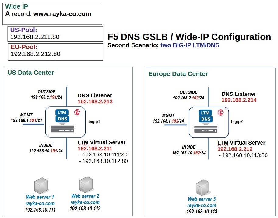
Example GSLB Topology: In this illustration, we have two data centers (US and Europe), each with a BIG-IP device (running LTM + DNS). Each data center has its own local virtual server for the application (e.g., 192.168.2.211 in US, 192.168.2.212 in EU) with web servers behind it. A Wide IP (www.rayka-co.com in this example) is configured on BIG-IP DNS to encompass both the US and EU pool of resources. BIG-IP DNS answers DNS queries for the Wide IP by potentially returning 192.168.2.211 (US pool) or 192.168.2.212 (EU pool)rayka-co.comrayka-co.com. A DNS listener is running on each BIG-IP DNS (192.168.2.213 and 192.168.2.214 respectively) to handle incoming DNS queries. If the US data center goes down or is too far for a given client, the BIG-IP DNS can respond with the EU virtual server’s IP, and vice versa, providing global high availability.
GSLB Configuration Overview
Configuring GSLB involves setting up a hierarchy of objects on the BIG-IP DNS module:
- Data Centers: Logical groupings representing each site.
- Servers: In GSLB terminology, a “server” is typically a BIG-IP device or a generic server that hosts resources. For BIG-IP integration, you define each BIG-IP (or each LTM instance) as a “Server” in the GSLB config, under the corresponding Data Center. This allows the GSLB module to monitor that BIG-IP and discover its virtual servers.
- Virtual Servers: These are the IP/Port combinations hosted in each data center that clients could be sent to. In our case, the virtual servers are the LTM VIPs in each site (e.g., 198.51.100.100 in US vs 203.0.113.100 in EU, or as in diagram, 192.168.2.211 vs .212). We will associate these with the GSLB Server objects.
- Pools (GSLB Pools): A GSLB pool contains one or more virtual servers (from different data centers). For example, a pool for “www.example.com” might contain the “VS in US” and “VS in EU”. The GSLB load balancing method (e.g., global round robin, topology-based, etc.) is set at the pool level.
- Wide IP: The Wide IP is the domain name that clients will query (e.g., www.example.com). The wide IP ties everything together – it maps a DNS name to one or more GSLB pools. When BIG-IP DNS receives a query for that name, it will choose a pool and select a viable server (IP) from that pool to return in the DNS responsef5.comf5.com.
Note: Ensure that the BIG-IP device you’re using has the DNS (GTM) module licensed and provisioned. In the GUI, under System > Resource Provisioning, the DNS module should be set to at least Nominal.
Configuration via GUI (BIG-IP DNS module)
Let’s configure GSLB assuming we have two BIG-IP LTMs (they could be two physical devices or two VCMP guests or two BIG-IP VEs). We’ll set up the GSLB on one of them (it will become the primary DNS that answers queries for the wide IP, and it can be synchronized to a secondary if needed).
- Define Data Centers: In the GUI, navigate to DNS > GSLB > Data Centers > Create.
- Create a data center for US_DC (Name: US_DC, Location: e.g., “US” – optional descriptive fields).
- Create another data center for EU_DC.
- Data centers are containers for organizational purposes and for certain monitoring groupings.
- Add BIG-IP Servers: Navigate to DNS > GSLB > Servers > Create. Here, we add each BIG-IP (or each group of resources) as a “Server” in GSLB:
- For the BIG-IP in the US data center:
- Name: e.g., BigIP_US.
- Product: BIG-IP System (since it’s an F5 device; this allows iQuery to be used).
- Data Center: select US_DC.
- Addresses: add the IP address that the GSLB module should use to communicate with that BIG-IP. Usually, this is the self IP or management IP that’s reachable from the GSLB device. For example, 10.0.0.10 (self IP of the US BIG-IP).
- Virtual Server Discovery: Enabled if the device is a BIG-IP. With BIG-IP product and discovery on, the BIG-IP DNS can automatically pull LTM virtual server objects from that BIG-IPrayka-co.com. (This requires the “gtm” synchronization and trust to be established, usually automatic if it’s the same device or via Add Server wizard which handles big3d/iQuery trust.)
- Health Monitor: choose BIG-IP Monitor (this uses the iQuery protocol to monitor the BIG-IP’s health). Ensure the BIG-IP’s
gtmlistener (iQuery, port 4353) is open between the devices. - Click Finished. The GUI may prompt for credentials or automatically use device trust. If the BIG-IPs are on the same device (like if one device has both LTM and DNS roles), it will simply add itself.
- Repeat Create Server for the BigIP_EU:
- Name: BigIP_EU,
- Product: BIG-IP System,
- Data Center: EU_DC,
- Address: e.g., 10.0.1.10 (self IP of EU BIG-IP),
- Virtual Server Discovery: Enabled, Monitor: BIG-IP, etc.
- Finish adding.
- After adding, you should see both servers in the list, each under the appropriate data center. If the BIG-IPs are reachable and iQuery trust is established, they should show as Available. If not, check the connectivity on port 4353 and consider running the gtm_add script via CLI to establish trust. (gtm_add is used to connect two BIG-IP DNS instances).
- For the BIG-IP in the US data center:
- Add the Virtual Servers (if not auto-discovered): If your LTM virtual servers were not auto-populated (auto-discovery works when the DNS and LTM are on the same box or already trusted), you might manually add the virtual server objects that GSLB will load balance:
- Go to DNS > GSLB > Servers, click on BigIP_US (for example). There will be a section to add Virtual Servers to that server.
- Click Add under Virtual Servers for BigIP_US. Provide:
- Name: e.g., vs_web_us.
- Destination: the IP and port of the local virtual server in that DC (e.g., 198.51.100.100:80 if that’s the VIP in US for the service, or the wildcard IP if using 0.0.0.0:80). This should match an actual VS on that BigIP if using product type BIG-IP. If discovery was on and working, it might already list the available virtual servers to select.
- You can also specify Service: e.g., 80 (if not part of destination spec).
- Link and Service check can be left default unless needed.
- Click Finished to add the VS.
- Add the corresponding vs_web_eu under BigIP_EU with its IP (e.g., 203.0.113.100:80).
- Create a GSLB Pool: Go to DNS > GSLB > Pools > Create.
- Name: e.g., www_example_pool.
- Type: A (assuming we are load balancing an IPv4 A record for a website).
- Members: Here we add the members which are the virtual servers we just defined. Select New Members -> pick BigIP_US -> vs_web_us and BigIP_EU -> vs_web_eu as members. You can assign each a fallback order or preference if needed. If you want active-active, keep them both enabled with equal settings. If you prefer one data center as primary, you could adjust the Order or Weight (e.g., order 0 for primary, 1 for secondary).
- Load Balancing Method: Choose how DNS responses are selected. Common methods: Round Robin (rotate between all available), Topology (based on geolocation of client’s DNS resolver vs. topology rules you set), Virtual Server Score or Lowest Round Trip Time, etc. For simplicity, use Round Robin or Global Availability (which always picks the first member unless it’s down, then next, etc.). Topology requires configuring topology records (mapping client IP regions to pool members) – beyond scope for now, but very powerful for geo-based routing.
- Click Finished to create the pool.
- Create the Wide IP: Navigate to DNS > GSLB > Wide IPs > Create.
- Name: The FQDN that clients will query, e.g., www.example.com.
- Record Type: A (assuming IPv4 service).
- Pools: Add the GSLB pool www_example_pool (the one we made) as a member of this wide IP. If you have multiple pools (for example, you could have one pool per region and use topology weighting between pools), you could add multiple and assign order/ratio, but in our simple case one pool is enough.
- Persistence: (Optional) If you want DNS responses to be consistent for a given client (so they don’t bounce between sites frequently), you can set a persistence TTL.
- Alternate and Fallback Pool: You can specify if the primary pool is down, what alternate pool to use (or None to use fallback). For simplicity, we have one pool so these can be none.
- Click Finished.
- DNS Listener: The BIG-IP DNS needs to actually answer DNS queries. By default, a BIG-IP may have a listener on *:53 (all addresses) for DNS if the DNS module is provisioned. If not, you should create one:
- Go to DNS > Delivery > Listeners > Listener List > Create.
- Name: e.g., dns_listener.
- Destination: You can use 0.0.0.0/0:53 to listen on all addresses on port 53, or specify a particular Self-IP if you only want to listen on a specific interface/address.
- VLANs: Specify which VLANs or interfaces should receive DNS queries (for security, e.g., Internet-facing VLAN).
- Finish to create.
- Ensure any firewall between clients and this BIG-IP allows UDP/TCP 53 to the BIG-IP.
At this point, the GSLB configuration is complete on the primary GTM (BIG-IP DNS). If you have a secondary, you would synchronize the config (BIG-IP DNS sync group) and have another listener there as well for redundancy.
Verification: To test GSLB, use a DNS query tool. For example, from a client, use nslookup or dig:
dig @<BIG-IP_DNS_IP> www.example.com
Replace <BIG-IP_DNS_IP> with the IP address of the BIG-IP’s DNS listener (could be its self IP). The response should be an A record for either the US or EU virtual server’s IP. Try running the dig multiple times; with Round Robin you should see it alternate between the two data center IPs. If one site is down (try marking the pool members down or disabling one of the GSLB servers), the BIG-IP DNS should only return the surviving site’s IP. You can simulate a client from a specific region (for topology-based configs) by using DNS query options or an external DNS test service.
On the BIG-IP, check DNS > GSLB > Wide IPs and click on www.example.com. It will show pool status and which IP is being returned. You can also use Statistics > DNS > GSLB to see Wide IP and pool statistics (like how many times each pool member was selected). In tmsh, tmsh show gtm wideip www.example.com will show you the load balancing decisions and status of pool members.
Configuration via CLI (tmsh) for GSLB
The GUI is easier for GSLB due to multiple object relationships, but here are example tmsh commands equivalent to the above:
# Create data centers
tmsh create gtm datacenter DC1
tmsh create gtm datacenter DC2

# Create servers for each BIG-IP
tmsh create gtm server BigIP_US datacenter DC1 product bigip \
     addresses add { 10.0.0.10 } monitor bigip
tmsh create gtm server BigIP_EU datacenter DC2 product bigip \
     addresses add { 10.0.1.10 } monitor bigip

# (If auto-discovery is not used, manually create virtual server entries under each gtm server)
tmsh create gtm virtual-server BigIP_US_vs destination 198.51.100.100:80 \
     address 198.51.100.100 service port 80 \
     server BigIP_US
tmsh create gtm virtual-server BigIP_EU_vs destination 203.0.113.100:80 \
     address 203.0.113.100 service port 80 \
     server BigIP_EU

# Create a GSLB pool and add members (the virtual servers)
tmsh create gtm pool a www_example_pool members add { BigIP_US:BigIP_US_vs {} BigIP_EU:BigIP_EU_vs {} } lb-method round-robin

# Create the Wide IP and assign the pool
tmsh create gtm wideip a www.example.com pool-lb-mode round-robin pools add { www_example_pool { order 0 } }

# Create a DNS listener on 0.0.0.0:53 (all IPv4)
tmsh create gtm listener /Common/dns_listener destination 0.0.0.0:53
Explanation of CLI steps:
- We created two data centers
DC1andDC2. - We then created two servers named
BigIP_USandBigIP_EU, marking them as productbigip(which implies they will use bigip monitor). We provided an address (could be the management or self IP that the GSLB will communicate with). Themonitor bigipmeans use the BIG-IP heartbeat monitoragility-dns-docs-17.readthedocs.ioagility-dns-docs-17.readthedocs.io. - We manually added virtual servers
BigIP_US_vsandBigIP_EU_vsunder each server, specifying the destination and linking to the server. - Then we created a GSLB pool of type A (
pool a) calledwww_example_pooland added the members referencing each server:virtual name. The syntax{ BigIP_US:BigIP_US_vs {} ... }is how tmsh identifies a GTM pool member by server name and virtual server name. - Then the wide IP is created as an A record for “www.example.com” and we attach the pool to it.
pool-lb-modeif set on wideip can override, but we set Round Robin on pool itself already. - Finally, we ensure a listener on UDP 53 (the default also covers TCP by default) to answer queries.
Verifying via tmsh: Use commands like:
tmsh list gtm wideip a www.example.com
tmsh show gtm pool www_example_pool members
tmsh show gtm server BigIP_US
These will show configured objects and their status (e.g., up/down). You can also run dig directly from BIG-IP’s bash (the BIG-IP has a dig utility in bash shell) to test name resolution.
Troubleshooting GSLB:
- If queries to the BIG-IP DNS are not getting answered, check that the listener is set up and that the DNS profile is running. Also ensure the queries are hitting the BIG-IP (use
tcpdump -ni <interface> port 53on the BIG-IP to see the DNS query packets). - If Wide IP isn’t responding with an expected pool member, check the status of servers and virtual servers in GSLB (the GUI GSLB > Servers screen will show each VS state). Possibly the BIG-IP thinks a server is down. Ensure the LTM in each DC is either discovered or the virtual server’s monitor status is up. If you used the BIG-IP monitor, the device should reflect the availability of those LTM objects. If the BIG-IP servers show as Offline in GSLB, the iQuery connection may not be working – try re-establishing trust (on each BIG-IP, run the ConfigSync > Device Trust for GTM or use the gtm_add utility via command line to link them).
- DNS caching can also confuse testing – ensure your local DNS client isn’t caching an old answer. Use
dig +nocacheor clear DNS cache between tests. - If using topology-based load balancing, make sure your Topology records (in DNS > GSLB > Topology) are configured and that the LDNS (client DNS) region can be determined. You might use Statistics > DNS > LDNS Probes to see from where queries are coming.
- Logs: BIG-IP GTM logs can be found in
/var/log/gtm(or/var/log/ltmalso receives some DNS logs). If a pool is failing, you may see hints there.
By implementing GSLB, users around the world can be automatically routed to the nearest or healthiest data center for www.example.com, and if an entire site goes down, BIG-IP DNS will stop sending users there, ensuring continuity.
Conclusion
In this guide, we covered configuring an F5 BIG-IP (v17+) for three common use cases: local load balancing of a web application, SSL/TLS offloading, and global server load balancing across multiple data centers. We used both the GUI and CLI (tmsh) to illustrate how to create nodes, pools, and virtual servers on the LTM, how to manage SSL certificates and profiles for HTTPS, and how to set up the BIG-IP DNS/GTM for wide IP load balancing.
By following these steps, an IT professional can set up a robust application delivery environment:
- Web Application Load Balancing: provides high availability and scaling within a site.
- SSL Offloading: improves performance and centralizes security for applications by handling encryption on the BIG-IP.
- GSLB (BIG-IP DNS): extends availability across sites, improves latency for global users, and adds disaster recovery capability at the DNS routing level.
Comments