


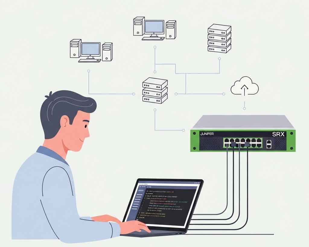
To configure a Juniper SRX firewall, you generally follow these high-level steps:
- Initial device setup (console/SSH access, root password, system parameters)
- Interface and zone configuration (assign IPs, create security zones)
- Policy and NAT definitions (firewall filters or security policies, source/destination NAT)
- Commit & verify (commit configuration, validate with
showandmonitorcommands).
Below, we unpack each of these phases in detail—answering “how to configure Juniper firewall” step by step, then expanding on best practices, common pitfalls, and verification techniques.
Table of Contents
1. Initial Device Setup
Before you can lock down traffic, you must bring the SRX online and establish secure access. The Guided Setup for branch SRX devices (SRX300/320/340/345/380) provides a streamlined CLI workflow:
- Console or SSH Access
- Connect via console cable (RJ-45-to-DB9 or USB) at 9600 baud, 8N1.
- Log in as root (no password) to start.
- Set Root Password This ensures no unauthorized root‐level logins.
pgsql
configure set system root-authentication plain-text-password commit- Create Administrative Users Following principle of least privilege, provision separate users rather than sharing a single root account.
pgsql
set system login user admin class super-user authentication plain-text-password commit- System Parameters – Host-name for device identification
– Time-zone & NTP for accurate logs
– DNS to resolve management and software-update hosts.
pgsql
set system host-name SRX-Branch-1 set system time-zone Asia/Singapore set system name-server 8.8.8.8
set system services ssh protocol-version v2 commit
2. Interface & Security Zone Configuration
Juniper SRX firewalls use zone-based security, grouping interfaces into trust/DMZ/untrust zones. Traffic flow is allowed only via explicitly defined policies between zones.
- Assign IP Addresses –
family inetfor IPv4; useinet6for IPv6.
pgsql
set interfaces ge-0/0/0 unit 0 family inet address 203.0.113.1/24 # Internet uplink
set interfaces ge-0/0/1 unit 0 family inet address 10.0.0.1/24 # Internal LAN- Create Security Zones Name zones to reflect role (e.g.,
untrust,dmz,trust) and bind each physical/logical interface.
pgsql
set security zones security-zone untrust interfaces ge-0/0/0.0
set security zones security-zone trust interfaces ge-0/0/1.0 - Enable Zone-based Policies
With zones in place, traffic is denied by default. You’ll need to define policies to permit specific flows (see Section 3).
3. Defining Security Policies & NAT
3.1. Security Policies
Security policies on SRX devices use a simple from-zone → to-zone model:
pgsql
set security policies from-zone trust to-zone untrust policy allow-web match source-address any destination-address any application junos-http
set security policies from-zone trust to-zone untrust policy allow-web then permit
commit- Match: Defines source/destination addresses, user roles, applications (AppSecure).
- Then: Action (
permitordeny).
You can also apply firewall filters (ACL-style) directly to interfaces for more fine-grained control. For EX-Series examples:
pgsql
set firewall family inet filter BLOCK_ICMP term 1 from protocol icmp
set firewall family inet filter BLOCK_ICMP term 1 then discard
set interfaces ge-0/0/2 unit 0 family inet filter input BLOCK_ICMP
– Terms: match conditions + action
– Apply: to port, VLAN, or L3 interface.
3.2. Network Address Translation (NAT)
For Internet‐bound traffic, you’ll almost always need source NAT (SNAT):
pgsql
set security nat source rule-set INTERNET_SNAT from zone trust
set security nat source rule-set INTERNET_SNAT to zone untrust
set security nat source rule-set INTERNET_SNAT rule snat-1 match source-address 10.0.0.0/24
set security nat source rule-set INTERNET_SNAT rule snat-1 then source-nat interface
commit- Rule-set: Groups related NAT rules.
- Rule: Matches traffic, then translates source to the firewall’s outbound IP.
4. Commit & Verification
After defining all configuration statements, issue:
nginx
commit check      # Validates syntax and resource usage
commit             # Applies config
Then verify with operational-mode commands:
- Cluster status (in HA setups):
show chassis cluster status - Zone/policy utilization:
show security policies hit-count - Firewall filters (EX-Series):
show firewall - Flow sessions:
show security flow session summary
Regularly monitor logs (show log messages, show security log) and consider automating alerts via SNMP or Junos Space.
5. Advanced Enhancements
Once your baseline is secure and stable, consider:
- AppSecure (AppID, AppQoE): Enforce policies by application rather than port.
- Intrusion Prevention (IPS) & Unified Threat Management (UTM): Tap into Juniper’s threat intelligence services.
- VPN:
- Site-to-site IPsec (phase 1/2 proposals, proxy-IDs).
- SSL VPN for remote users.
- High Availability:
- Chassis Cluster active/standby pair with redundancy groups (RG0 for control plane, RG1+ for data plane).
- Monitor with
show chassis cluster informationandmonitor chassis cluster status.
For each feature, Juniper’s documentation provides in-depth CLI examples and best-practice recommendations.
Comments